A Guide to Understanding Walk-In Ovens

Walk-in ovens are not standard products — they are configurable systems built around your process. This guide explains the major variables, construction methods, airflow strategies, and specification framework that define every walk-in oven.


1. What Is a Walk-In Oven?

Walk-in ovens are often talked about as if they are standard products, but in practice, most industrial walk-in ovens are configurable systems built around process requirements. Once you move beyond smaller cabinet-style equipment, most walk-in ovens are still engineered to order and built to order.

Rather than showing millions of possible combinations, the better way to think about walk-in ovens is not as fixed model numbers, but as configured systems built from a set of architectural and performance choices. Most so-called "standard" walk-in ovens are still being configured around the customer's workpiece, thermal process, facility constraints, and performance expectations.

In many cases, manufacturers are adapting prior designs rather than delivering a truly optimized oven architecture for the specific process. Precision Quincy takes a different approach: each walk-in oven is engineered around the application from the ground up.

Why This Guide Exists
This guide is intended to help engineers, buyers, and process owners understand the main variables that define a walk-in oven before starting a specification or quote request. It is a high-level overview — not a substitute for application engineering.

2. The Key Ingredients That Define a Walk-In Oven

Every walk-in oven is defined by a set of interconnected variables. Rather than trying to catalog every permutation, it is more useful to understand these major "ingredients" and how they interact.

PQ_Icon_TempRange

Temperature Range

From approximately 5°F above ambient up to 1500°F. Temperature drives insulation thickness, shell construction, heat source selection, and material choices throughout the oven.

PQ_Icon_Airflow

Airflow Configuration

Horizontal-vertical, full horizontal, vertical up/down, alternating. The airflow pattern must be matched to the product arrangement, loading method, and heat-transfer requirements.

PQ_Icon_HeatSource

Shell & Construction

Insulated panel, can-constructed, pin-style, or ceramic fiber module. Each has tradeoffs in thermal growth management, structural capacity, serviceability, and shipping.

PQ_Icon_HeatSource

Heat Source & Controls

Gas-fired or electric. Controls range from basic setpoint to ramp/soak recipes and cascade control for process-sensitive products.

PQ_Icon_Air_Change_Level

Air Change Level

How aggressively the oven recirculates air. Drives uniformity, heat-transfer rate, and recovery speed. Ranges from extra-low to extra-high depending on the application.

PQ_Icon_Uniformity_Level

Uniformity Level

Typically ±10°F below 1000°F and ±15°F above. Tighter or looser specs can be engineered depending on the process. Driven by shell quality, airflow, and recirculation rate.

PQ_Icon_Controls_Automation

Controls & Automation

From single-setpoint controllers through multi-zone ramp/soak recipes. Control complexity depends on the process sensitivity, compliance requirements, and production workflow.

PQ_Icon_NFP86

NFPA 86 Class

Class A (flammable solvents or volatiles present) or Class B (no flammable volatiles). Classification determines safety systems, exhaust, purge interlocks, and ventilation requirements.

3. Temperature Ranges

Walk-in oven temperature ranges span from approximately 5°F above ambient up to 1500°F. Temperature is the single most influential variable in walk-in oven design because it directly drives insulation thickness, shell construction type, heat source selection, material choices for interior surfaces, gasket and seal design, and structural engineering for thermal growth.

Insulation thickness generally increases with maximum operating temperature, but the relationship is not always linear. A lower-temperature oven may still use thicker wall construction — such as a 6-inch insulated shell — if the goal is to improve energy efficiency and reduce heat loss to the facility. Conversely, insulation can never be reduced below what is required for the operating temperature and safe outer shell temperatures.

Temperature and Construction Are Linked
As operating temperature rises, the oven experiences more thermal growth, more demanding insulation requirements, and higher structural loads from temperature differentials. This is why higher-temperature walk-in ovens tend to use different construction methods than lower-temperature ones — not just thicker insulation on the same shell design.

4. Shell & Construction Types

There are multiple shell construction styles used in industrial walk-in ovens. The major tradeoffs involve thermal growth management, structural load path, insulation support, serviceability, shipping method, and overall cost. There is no single best construction for every application.

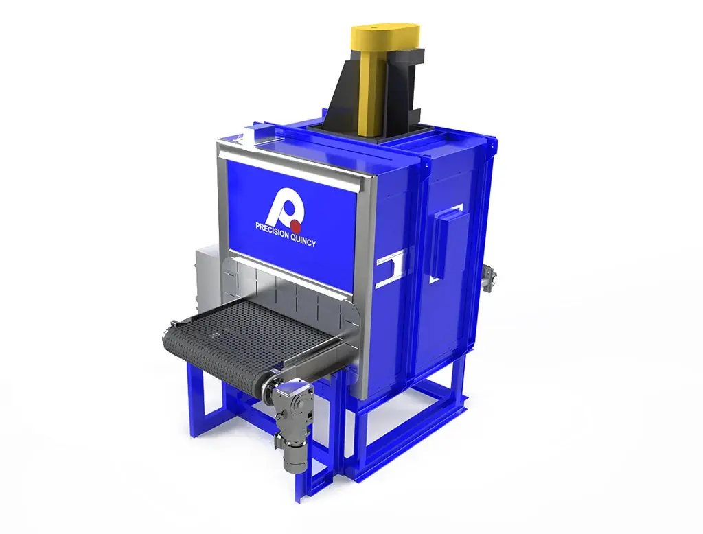
Insulated Panel Construction

In this approach, the insulated panel itself serves as both the insulated barrier and a structural element. Because the inner steel skin runs at a higher temperature than the outer skin, the panel behaves like a bimetal spring as the oven heats up — the inner surface wants to expand more than the outer surface, which can cause panel warping. Additional structural steel is often added to control that warping.

This creates a fundamental tradeoff: the same panel is being asked to provide insulation and carry structure. Modifying the connecting geometry between inner and outer skins can reduce thermal-growth forces, but may also weaken the panel structurally. Insulated panel construction is most attractive for lower-temperature and lower-cost applications, especially when the oven is not extremely large. Panels can often be shipped flat-packed for efficient field assembly.

Can-Constructed Shells

In can-constructed ovens, the inner and outer shells are more independent from each other. The outer structure supports the external shell and major equipment such as fans, heat systems, and exhaust devices. Inner liners or pans typically support the insulation load, connected at structural boundaries like the base, perimeter framing, or door areas. This creates a different load path than insulated panels — the inner liner system carries much of the insulation weight rather than the panel acting as a single combined structural-insulated member.

Supported-Cladding / Semi-Can Construction

A variation where an outer structural shell or frame carries the primary load while interior cladding mainly protects the insulation from the oven air stream. The inner cladding is attached through stand-offs, pins, or other features that allow thermal movement. This reduces the need for the inner liner system to carry the entire insulation load from above — related to can construction, but with a different load path and thermal-growth strategy.

Pin-Style Construction

The outer shell or structural frame carries the main load. The inner cladding is not a major structural element — its purpose is to protect the insulation from erosion or damage caused by recirculation airflow. The cladding is divided into smaller overlapping sections so it can expand and contract freely, attached by pins at intervals back to the outer structure. This approach makes thermal growth much easier to manage and is generally much less sensitive to large-scale warping than insulated panels. Pin-style construction can also allow future re-insulation or cladding replacement. In many larger or hotter oven applications, this is one of the more robust approaches.

Ceramic Fiber Module / Furnace-Style Construction

Structural outer framing with ceramic fiber modules attached to the inside of the shell using studs. The modules are often exposed to the interior unless a protective mesh or rigidizer is applied. More similar to furnace construction. In convection applications, airflow management or protective measures may be needed to reduce erosion of the exposed insulation. Like pin-style, the outer shell carries the structural load, so differential inner-versus-outer growth is less of a system-level problem.

General Tradeoff Principle

Constructions where the outer structure carries the load and the inner thermal barrier can move independently tend to scale better as ovens become larger or hotter. Pin-style and ceramic-fiber-module constructions can both reduce expansion and contraction problems compared with systems where the hot inner and cooler outer skins are rigidly tied together.

Pressure-Shell Consideration

In some pressurized duct or heat-chamber sections, it may make sense to place the heavier structural shell on the hot side and wrap insulation around the outside of that pressure shell. This can be structurally advantageous for certain ducted sections, but if the hot inner shell is rigidly fixed to surrounding structure, thermal growth must be managed carefully with sliding supports, expansion joints, and other provisions.

5. Sizing & Dimensional Ranges

These ranges represent practical architectural capability — not a fixed catalog of stock models. Oven size should be driven first by the workpiece, required clearance, and loading method.

Interior Widths

36–240+

inches

Interior Depths

36–1,200+

inches

Interior Heights

60–240

inches

Temperature Span

~Ambient–1500

°F

How Oven Size Is Determined

Oven size should be driven first by the workpiece and required clearance around the work. Product dimensions alone do not always define the required chamber size — the loading method can become a major sizing constraint even when the product itself is smaller. Common loading approaches include forklifts, pallet jacks, rigged loads, carts, roller-supported loads, or pusher/extractor-style handling.

The required loading and unloading method should be considered together with the temperature conditions under which loading and unloading occur. Safety and damage prevention — such as preventing a forklift from striking the oven shell or interior — also affect practical sizing. Facility constraints like available floor space, ceiling height, and access limitations further influence the envelope.

Shipping and Installation

As overall oven size increases, engineering must account for shipping limitations, facility access constraints, sectionalization for transport, field assembly, and structural and thermal considerations tied to the installation site. Larger ovens may be shipped in sections, assembled on site, or engineered around facility access and installation constraints.

6. Loading & Product Considerations

Industrial walk-in ovens cannot be sized only by asking whether the product physically fits in the chamber. The way the product is loaded and arranged strongly affects heat transfer, airflow, and usable throughput. A chamber that appears large enough on paper may perform poorly if the product loading blocks circulation air.

Airflow and Product Arrangement

In most forced-convection walk-in ovens, product should not be loaded so tightly that airflow cannot move through the load and return to the recirculation system. If an 8 ft × 8 ft × 8 ft work chamber is completely packed with product, the oven may not heat effectively because the airflow path is blocked. Product loading should consider both airflow across the product and the return path of cooler air back to the recirculation system.

Product Heating and Load Geometry

The way product is grouped, stacked, or contained has a major effect on heating time and process consistency. A tightly packed basket of parts heats very differently than the same parts spread across shallow trays. Parts in the middle of a basket that are not exposed to moving air rely mainly on radiant heat and conduction from hotter outer parts — meaning outer parts heat much faster than the interior of the load.

In many cases, shallow trays, more open loading patterns, or separated load sections can improve heating consistency and reduce heat-up time. Different airflow architectures can also support different loading strategies. For example, two shelved carts placed side by side with a gap between them may allow a full-height horizontal-vertical pattern to move air around the carts and turn the air in the center.

Key Principle

Airflow pattern and product arrangement must be considered together, not separately. Product position inside the oven affects the actual air temperature and velocity seen by the part. In a full-horizontal pattern, product farther from the air supply may be contacted by air that has already given up energy to product upstream.

7. Airflow Categories

Airflow configuration is one of the most important design decisions in a walk-in oven. The pattern determines how heat is delivered to the product, how temperature uniformity is maintained, and how the oven handles different loading arrangements.

Horizontal-Vertical
Horizontal-Vertical
Full Height Horizontal-Vertical
Full Horizontal Side-to-Side
Full Horizontal Front-to-Back
Vertical Up
Vertical Up
Alternating Full Horizontal

Horizontal-vertical is the default on most walk-in ovens, where supply air enters from one side and returns through a combination of horizontal and vertical flow paths. Full horizontal patterns push air from one side to the other (or front to back), best suited for shelved or cart-loaded product. Vertical patterns push air up or down through the load, suited for applications where product is arranged in layers with open paths between them.

Gentle Distribution vs. High-Velocity Discharge

Not every process benefits from maximum local air velocity. Some products require gentle, evenly distributed airflow to avoid disturbing the load. In those cases, the discharge system uses many openings or louvers so air enters the chamber more evenly at lower local velocity. Other processes benefit from much more aggressive discharge designs, including nozzle-based systems intended to break up the surface boundary layer and drive very high local heat-transfer rates. The right discharge strategy depends on the product, allowable product disturbance, and required heat-transfer performance.

8. Air Changes, Heat Transfer & Airflow Intensity

When thinking about heating a product in a forced-convection oven, it is useful to think in terms of three practical limits: the product itself, the heat-transfer rate into the product, and the total heat power available from the oven.

Impingement vs. Non-Impingement

In impingement-style heating, air is directed at the product surface with meaningful local velocity, continually replacing the boundary-layer air at the surface to increase heat-transfer rate. In non-impingement forced convection, air movement still improves heat transfer compared with stagnant air, but the local rate is lower because the air at the surface is not being disrupted as aggressively.

The general goal is to maximize the difference between product temperature and the temperature of the moving air actually contacting the product. If the air next to the product becomes stagnant, slow-moving, or already cooled by upstream product, heating rate drops. If the oven continually replaces that boundary-layer air with hotter, more energetic moving air, the product heats faster.

Air Changes per Minute as a Relative Sizing Tool

Air changes per minute are a practical shorthand for how aggressively the oven is recirculating and redistributing heat. They are not a perfect measure of product heating performance, but they are useful for standardizing relative airflow intensity across oven sizes and temperature ranges.

Higher air-change rates generally reduce chamber temperature drop, improve mixing, and support faster recovery and better empty-oven uniformity. Lower air-change rates may be acceptable where product heating demand is modest, shell losses are lower, or process sensitivity requires gentler airflow. In very large ovens, the physically achievable air-change rate may drop because the required fan horsepower and duct size become impractical.

Why More Air Changes Improve Uniformity

If recirculated air remains in the chamber too long before being reheated and redistributed, it continues losing energy to the product, shell, floor, and exhaust path. As recirculation rate increases, the total energy removed from the air is spread across more moving air mass, so the temperature drop through the chamber becomes smaller. However, good empty-oven uniformity does not automatically mean strong product heat-transfer performance — an oven can appear reasonably uniform while still transferring energy into the load too slowly.

Relative Performance Categories

For configuration purposes, it is useful to think of both air-change level and heat-power level as relative categories rather than one fixed formula. Two ovens of the same size and temperature may be configured very differently — one may need gentle airflow and low heat input for a light composite load, while another may need aggressive recirculation and much higher heat input for a dense metal load.

Recirculation Intensity

Ranges from extra-low through extra-high. A medium air-change level for one temperature range may correspond to a low or very-low relative level at a much higher operating temperature because air density changes with temperature.

Heat-Power Level

Ranges from extra-low through extra-high relative to oven volume, temperature, and process demand. Products that absorb heat aggressively require more air movement and heat replenishment than low-demand loads.

9. Uniformity & Performance

Default empty-oven uniformity for ovens below 1000°F is typically ±10°F. For ovens above 1000°F, the default is typically ±15°F. Tighter or looser uniformity can be specified depending on the process requirement.

The main drivers of empty-oven uniformity are shell insulation and wall thickness, shell type or construction style, and air changes per minute. Uniformity is not defined by size and temperature alone.

Shell Quality and Uniformity

Air changes per minute are only one part of the uniformity picture. Wall insulation level, shell construction type, floor construction, and thermal bridging all affect how much cold influence enters the chamber. A poorer shell may require more recirculation just to compensate for shell losses and local cold spots. A better shell can often achieve the same empty-oven uniformity with less recirculation energy.

Floor design is especially important in walk-in ovens because a large concrete floor or poorly insulated base can become a major sink for heat and a major source of chamber non-uniformity. In some high-performance applications, floor heating or other special floor strategies may be needed because recirculation alone cannot fully compensate for floor losses.

Ramp Rate and Product Protection

Maximum heat-transfer rate is not always desirable. Some products need controlled ramp rates to avoid internal thermal gradients, warping, trapped volatiles, premature curing, or other process defects. Control strategies such as ramp/soak recipes, cascade control, or staged heating can limit how quickly the air temperature rises relative to the product. This is especially important for products with poor internal conductivity, layered construction, cure-sensitive chemistry, or tight distortion limits.

10. Heat Power & Production Load

Oven sizing should not be based only on chamber size and maximum temperature. The heat power requirement depends heavily on product weight, product material, required heat-up rate, and process setpoint.

A relatively small oven with a very heavy product load can require more heat power than a much larger oven with a lighter load. For example, a 750°F oven heating only 500 lb of product may require much less heat power than a 300°F oven heating 100,000 lb of product. One useful way to think about oven capacity is the amount of product mass that must be brought from ambient to setpoint within a required time.

Warm-Up vs. Sustaining Load

Many ovens use their highest heat power mainly during warm-up and product-recovery periods, then drop to a much lower sustaining load once the oven and load are near steady state. If the process can tolerate a slower ramp-up period, installed heat power can often be reduced to save first cost.

Future-Proofing

Future process changes should be considered when selecting heat power so the oven is not undersized for later use. Heat power requirements may also differ by heat source — gas- and electric-heated systems do not always have the same practical utility and exhaust tradeoffs.

11. The Three-Layer Specification Framework

A walk-in oven specification is better understood as three layers than as a single model number. This framework provides a structured way to think through the requirements before requesting a quote.

Layer 1

Customer Process Requirements

What is the workpiece? How is it loaded into the oven? What process is taking place? What are the facility constraints, utility requirements, and production needs?

Layer 2

Thermal Process Requirements

Required operating temperature or range. Empty-oven uniformity requirement. Heating rate or production heat-power requirement. Airflow style and air-change level. VOC/solvent handling requirements if applicable.

Layer 3

Equipment Concept & Architecture

Shell thickness and construction type. Heat chamber location and duct architecture. Airflow configuration. Controls package. Heat source type. Serviceability, shipping, and installation layout.

Basic Selection Logic

Selection should start with the workpiece. Next, define the required process temperature range and the target air temperature around the product. Then define the thermal performance requirements — uniformity, air changes, heating rate, and VOC handling if applicable. Based on the product design, loading pattern, and dimensional constraints, airflow style is often one of the next major decisions. Facility limits such as floor space, ceiling height, and pass-through requirements also influence the oven layout. Final configuration should be based on all three layers considered together.

Configuration Snapshot Concept

A walk-in oven configuration can be described through a structured set of variables. The following fields represent the main decisions that define any walk-in oven:

Configuration Variable
Example Value
Oven process type
Annealing
Product material type
Steel
Product weight
7,000 lb
Interior width
96 in.
Interior depth
144 in.
Interior height
96 in.
Maximum temperature
850°F
Operating temperature range
250°F to 850°F
NFPA 86 class
Class B
Airflow configuration
Horizontal-vertical
Relative air-change level
Medium
Relative heat-power level
Medium
Uniformity level
±10°F
Shell / insulation
6 in. insulated shell
Heat source type
Natural gas direct-fired
Heat chamber location
Top mount
Door type
Biparting swing doors
Oven floor type
Insulated floor with cart guide tracks
Supply orifice type
Louvered supply
Shipment requirement
Sectionalized shipment
Controls level
Ramp / soak controller

12. PQ Product Family: HD Series Heavy-Duty Walk-In Ovens

Precision Quincy's HD Series walk-in ovens are engineered to order for manufacturers who need a heavy-duty batch oven matched to their process, product size, loading style, facility constraints, and operating temperature. The line is organized into four temperature families covering applications from 500°F through 850°F.

The HD Series is built around the combination of high airflow, high energy transfer, and tight temperature uniformity. Features include full top return ducting, high-volume air recirculation, reinforced steel doors, heavy-duty welded construction, oversized mineral wool insulation, factory wiring and testing, and Class A or Class B availability. These ovens can be configured with either electric heat or fuel-fired heat.

Temperature Families

HD4

500°F max

4" insulated wall

HD5

650°F max

5" insulated wall

HD6

750°F max

6" insulated wall

HD7

850°F max

7" insulated wall

As temperature class increases, the package grows not only in insulation thickness but also in air-moving and heating capacity. Fuel input scales from approximately 390,000–400,000 BTU/hr in HD4/HD5 examples to 600,000 BTU/hr in HD6 and over 1,000,000 BTU/hr in HD7. Recirculation power increases from 5 HP up to 10 HP in published examples.

Two Mechanical Configurations

Configuration A

Back-Mount (B)

Rear-mounted heat chamber with full top return duct. Designed for facilities where ceiling height is the primary constraint. Offers a low external height package with rear service access.

  • Low external height package

  • Longer footprint acceptable

  • Rear service access preferred

  • Horizontal-vertical airflow standard

  • Optional full-horizontal airflow on selected models

  • Cart guide tracks on larger units

Configuration B

Top-Mount (T)

Overhead heat chamber with standard top return duct. Designed for facilities where floor space is the primary constraint. Offers a smaller overall footprint.

  • Smaller floor footprint

  • Vertical space is available

  • Same temperature family progression

  • Horizontal-vertical airflow standard

  • Similar process coverage to back-mount

  • High airflow rate

Representative Published Specifications

Model
Family
Setup
Interior (W×D×H)
Max Temp
Recirc (CFM)
Motor (HP)
Heat (BTU/hr)
Wall
HD4B-410-8
HD4
Back
48×120×96 in.
500°F
6,400
5
400,000
4"
HD5B-406-8
HD5
Back
48×72×96 in.
650°F
4,416
5
390,000
5"
HD6B-806-6
HD6
Back
96×72×72 in.
750°F
7,200
7.5
600,000
6"
HD7B-708-8
HD7
Back
84×96×96 in.
850°F
12,544
10
1,020,000
7"
HD4T-508-8
HD4
Top
60×96×96 in.
500°F
6,400
5
400,000
4"

These are representative published examples. The HD Series is engineered to order — actual configurations are matched to the application, process, and facility.

Ready to specify a walk-in oven?

Our engineering team can help match the right architecture, temperature class, airflow configuration, and controls package to your process.