
Project Number: 5385
Continuous Tempering Oven System for Heat-Treated Wear Parts (Construction Edges & Dozer End Bits)
.webp?width=1400&name=5385%20BLACKCAT%20(2).webp)
.webp?width=1400&name=5385%20BLACKCAT%20(3).webp)
.webp?width=1400&name=5385%20BLACKCAT%20(4).webp)
.webp?width=1400&name=5385%20BLACKCAT%20(5).webp)
.webp?width=1400&name=5385%20BLACKCAT%20(6).webp)
.webp?width=1400&name=5385%20BLACKCAT%20(7).webp)
.webp?width=1400&name=5385%20BLACKCAT%20(8).webp)
Overview
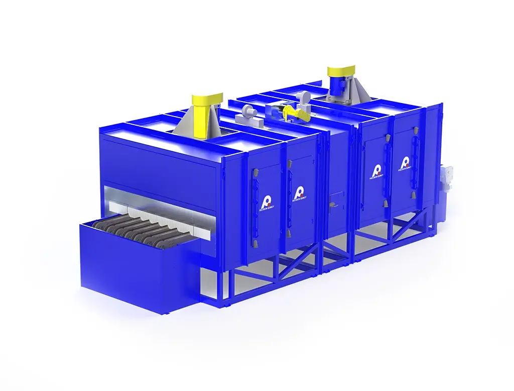
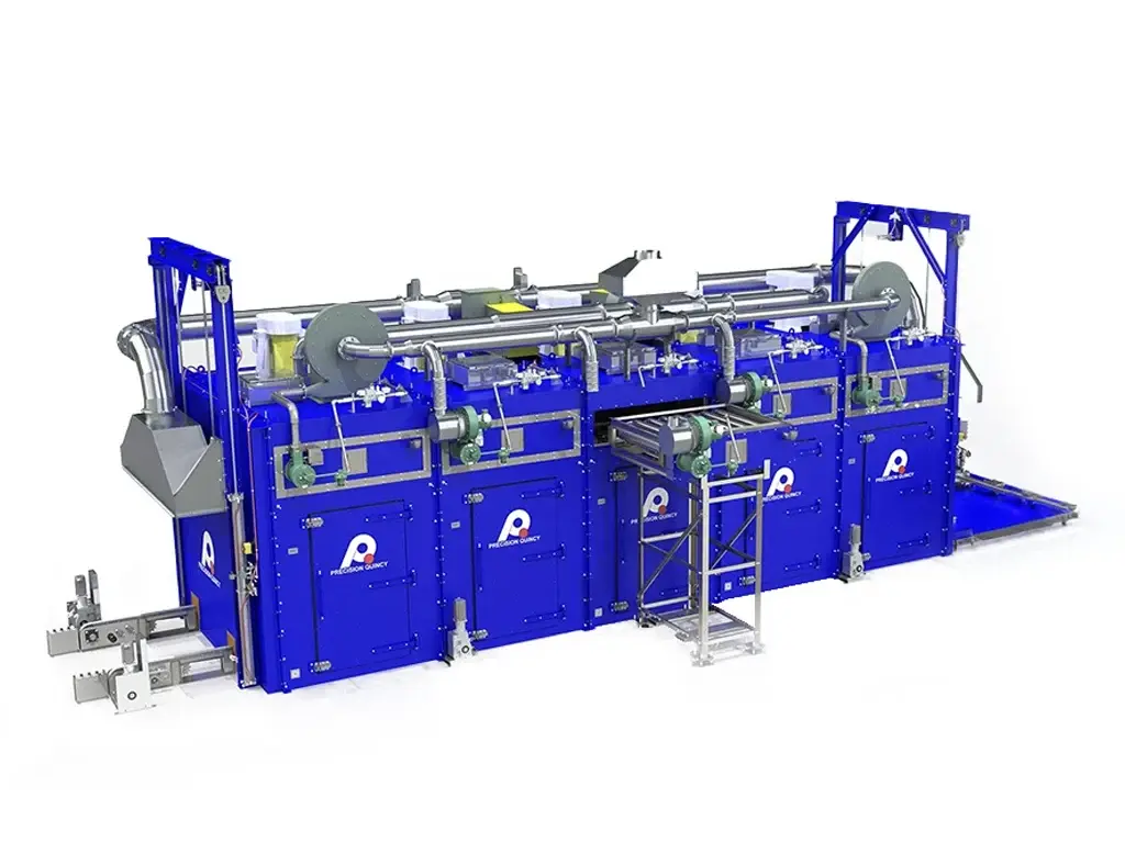
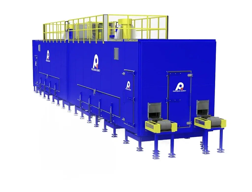
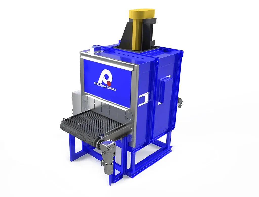
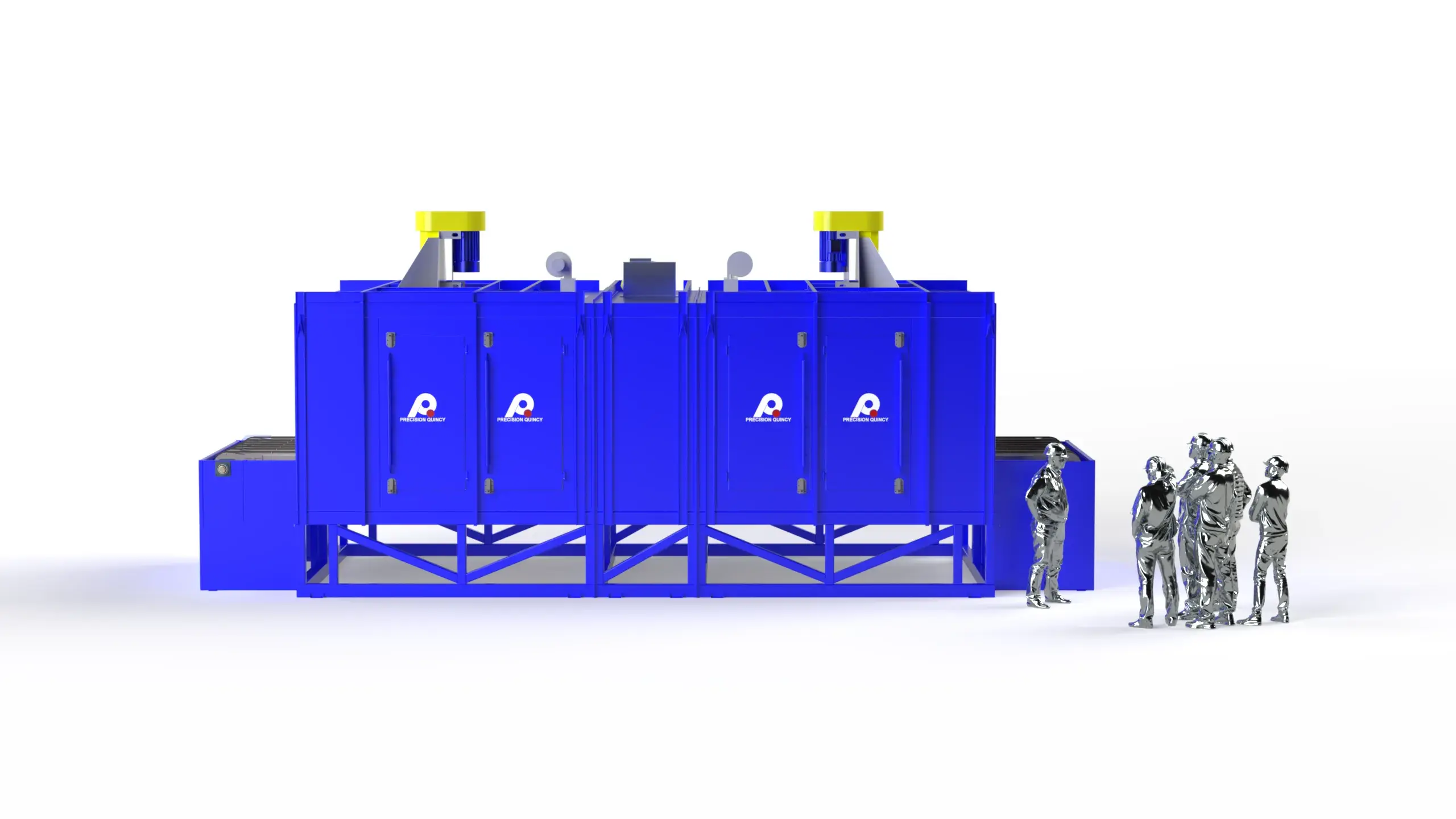
Precision Quincy engineered a continuous, single-pass tempering oven system to support heat-treated wearpart production, including construction edges, dozer end bits, and weld-on wear parts produced from boron and high-spec alloy steels. Following austenitizing and quenching upstream, the customer required controlled tempering to increase toughness and workability while preserving high hardness for abrasion resistance.
The system was designed for straight-through production with crane loading and unloading at each end, processing parts up to 10 ft long (up to 8 in tall; typical ~3 in) at a production rate of 5,000 lb/hr. The oven is a two-zone, direct-fired natural gas design (NFPA 86 Class A) with a typical operating range of 430–580°F (221– 304°C) and a design maximum of 600°F (316°C).
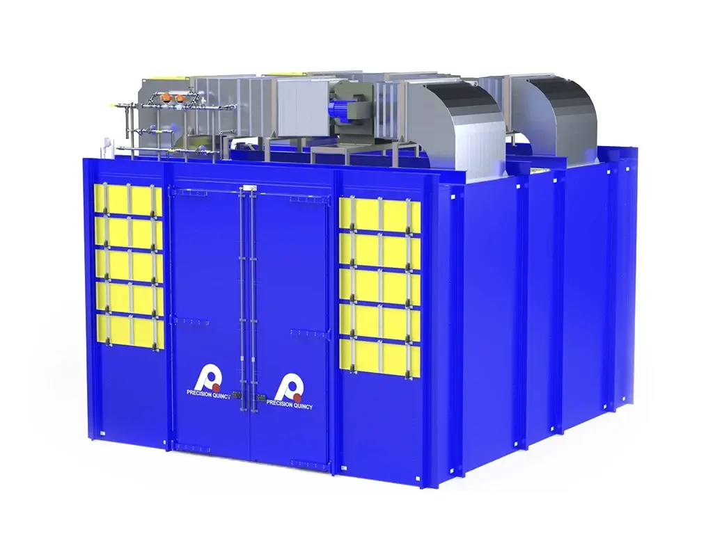
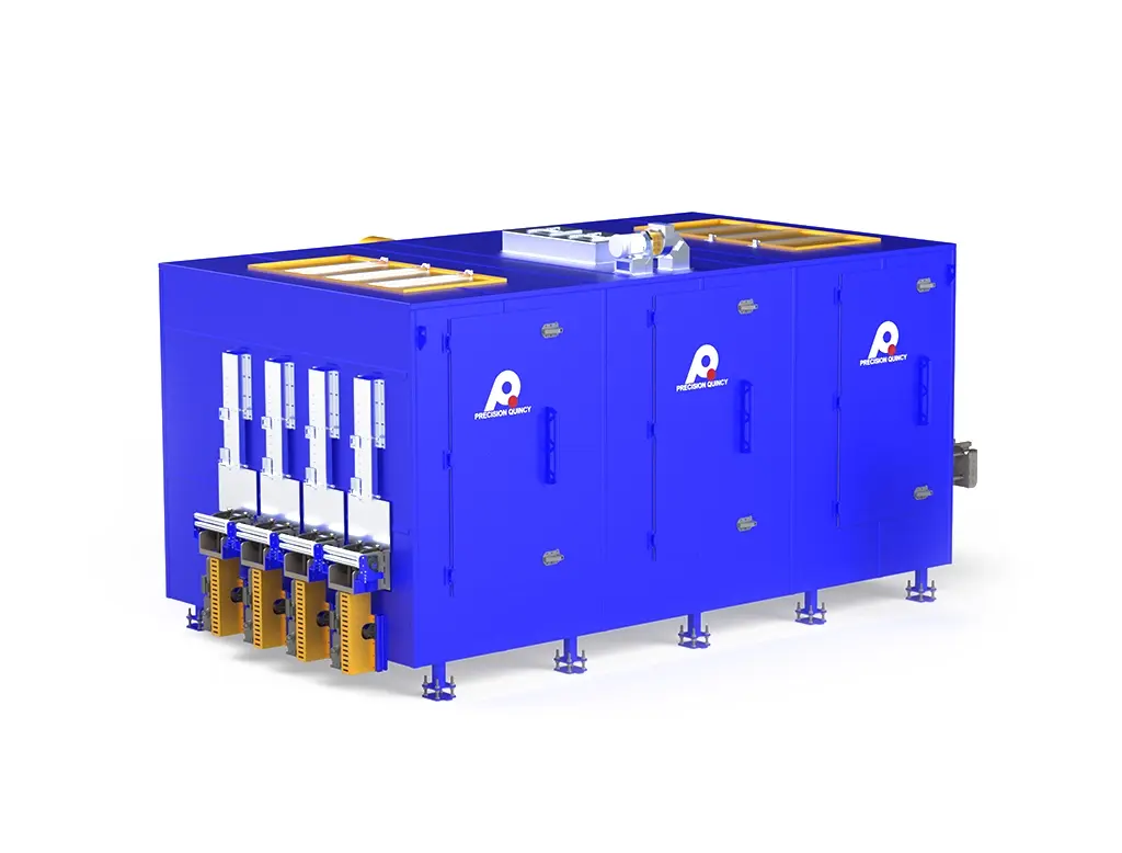
To deliver the tempering heat transfer requirement, the oven uses vertical down impingement through 2 in round nozzles at 4,000 FPM, driven by (2) 36 in NYB PLR recirculation fans rated 24,000 CFM each at 4.0 in. w.c. (48,000 CFM total) with 25 HP motors. The conveyor system is a seven-row engineering chain running on steel rails with a canary take-up system, providing 6,000 lb total conveyor capacity (evenly distributed). Process exhaust is provided by a PQ15 exhauster rated 950 CFM, mounted between zones. The insulated panel shell is structural-steel reinforced with 5 in walls containing 6 lb density mineral wool, mounted on a stand. Overall equipment dimensions are 170 in H × 170 in W × 404 in D, designed to ship in three sections.
The customer required a continuous tempering process to support production of heat-treated wear parts, including dozer end bits, construction edges, and weld-on wear parts produced from boron and high-spec alloy steels.
PROCESS OBJECTIVE (TEMPERING AFTER QUENCH)
- Temper quenched parts to increase toughness and workability while maintaining maximum abrasion resistance.
- Achieve target hardness ranges by product family, with minimal reduction in hardness during tempering.
PRODUCT / MATERIAL FAMILIES
- Dozer end bits: high-spec alloy X14 steel.
- Construction edges: “black carbide” through-hardened edges made from boron steel (15B30).
- Weld-on wear parts: through-hardened components.
HARDNESS TARGETS (OUTCOME REQUIREMENTS)
- Weld-on parts through-hardened to approximately 353–390 BHN.
- Other boron parts hardened to approximately 410–512 BHN.
THROUGHPUT REQUIREMENT
- Production rate requirement: 5,000 lb/hr.
PART ENVELOPE / HANDLING CONSTRAINTS
- Maximum part length: up to 10 ft.
- Maximum part height: up to 8 in (typical ~3 in).
- Material flow: single-pass, straight-through line.
- Loading/unloading: crane-loaded at each end.
UPSTREAM PROCESS CONTEXT (BASIS FOR TEMPERING)
- Parts are heat-treated upstream: austenitized at approximately 900–950°C, then quenched in oil.
- Tempering stage is performed in this oven.
VALIDATION / ACCEPTANCE
- Acceptance based on hardness testing.
The tempering process requirements are driven by the need to preserve high hardness for abrasion resistance while increasing toughness and workability after quenching.
TEMPERATURE REQUIREMENTS
- Typical operating range: 430–580°F (221–304°C).
- Design maximum operating temperature: 600°F (316°C).
- Zone-specific: Zone 2 typical setpoint 410°F (210°C).
HEAT TRANSFER / AIRFLOW DELIVERY REQUIREMENTS (IMPINGEMENT)
- Airflow pattern: vertical down impingement onto wear parts, then return up the sides of the work chamber.
- Nozzles: 2 in diameter round nozzles, staggered spacing.
- Nozzle discharge velocity: 4,000 FPM.
- Total recirculation airflow: 24,000 CFM × 2 = 48,000 CFM total.
- Temperature uniformity at nozzle discharge: ±10°F.
SAFETY / CLASSIFICATION BASIS
- Product VOC content: none (as stated).
- Exhaust requirement: exhaust provided for product combustion.
- NFPA 86 classification: Class A.
VALIDATION / ACCEPTANCE BASIS
- Acceptance based on achieving required hardness outcomes (BHN targets) via hardness testing.
To deliver the customer's tempering requirements at the required throughput and part envelope, Precision Quincy developed the following equipment concept and architecture.
OVERALL CONCEPT
- Continuous tempering oven, single-pass, straight-through.
- Handling concept: parts are crane-loaded at the infeed and crane-unloaded at the discharge.
- Conveying method: continuous conveyorized system (seven-row engineering chain).
TWO-ZONE DIRECT-FIRED HEATING ARCHITECTURE
- Oven operated as two independent temperature zones, each with its own burner and recirculation system.
- Zone 1 burner: 2.5 MMBtu/hr — Access Combustion LP30.
- Zone 2 burner: 1.0 MMBtu/hr — Access Combustion LP12.
- Fuel/firing: direct-fired natural gas.
- Gas train: CSA compliant (Canadian fuel-train basis). Inlet pressure: 2 PSI. Total full-flow rate: 3,500 CFH.
RECIRCULATION / NOZZLE IMPINGEMENT ARCHITECTURE
- Recirculation fans: (2) New York Blower 36 PLR, 24,000 CFM each at 4.0 in. w.c., 25 HP motor each.
- Airflow delivery: 2 in round nozzles in a staggered pattern producing 4,000 FPM discharge velocity.
- Flow path: vertical down impingement onto the product, exit/return along the sides, reheated, and recirculated back to the fan inlets.
EXHAUST ARCHITECTURE
- Exhauster: PQ15, 950 CFM total, mounted between the two zones.
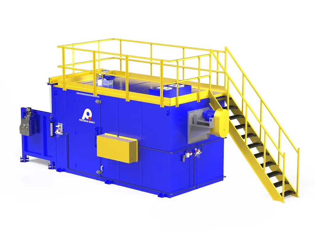
CONVEYOR / HANDLING CONCEPT
- Conveyor type: seven-row engineering chain conveyor running on steel rails with canary take-up.
- Capacity: 1,000 lb per rail; 6,000 lb total (evenly distributed).
- Drive: Nord helical bevel gearbox. Conveyor speed: 3 ft/min (VFD-controlled). Conveyor motor: 3/4 HP.
- Strand spacing: 0, 16, 28, 40, 52, 64, 80 in.
CONSTRUCTION / SHELL
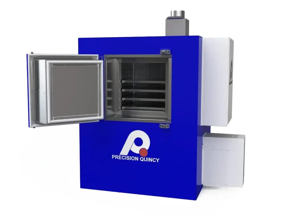
- Shell style: structural-steel reinforced insulated panels.
- Wall thickness: 5 in with 6 lb density mineral wool insulation.
- Mounting: oven sits on a stand.
ACCESS / EXPLOSION RELIEF / SERVICEABILITY
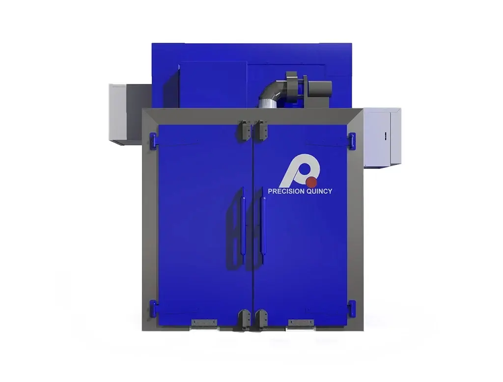
- Five access doors per side used for explosion relief and service access.
INSTRUMENTATION / SAFETY INTERLOCKS
- Airflow proving: airflow switch on each recirculation fan.
- High-limit temperature controllers located in front of each fan in the heat chamber.
- Each zone has its own work-chamber high limit.
ELECTRICAL / CONTROLS
- Temperature controllers: SSI-804 (one per zone).
- PLC/HMI: Allen-Bradley Micro850 PLC with 10 in HMI.
- Control enclosure: NEMA 1. Power: 460V, 3-phase, 60 Hz; 83 A total.
- Power: 460V, 3-phase, 60 Hz; 83 A total.
OVERALL DIMENSIONS / SHIPPING CONCEPT
- Equipment overall dimensions: 170 in H × 170 in W × 404 in D.
- Shipping: designed to split into three pieces for shipment.
| OVEN CONFIGURATION | |
|---|---|
| Type | Continuous, single-pass, straight-through tempering oven; two-zone; vertical down impingement |
| NFPA 86 Classification | Class A |
| Typical Operating Range | 430–580°F (221–304°C) |
| Design Maximum Temperature | 600°F (316°C) |
| Throughput | 5,000 lb/hr |
| Max Part Length | Up to 10 ft |
| Max Part Height | Up to 8 in (typical ~3 in) |
| Conveyor Load Height / Pass Height | 62 in |
| Equipment Overall Dimensions | 170 in H × 170 in W × 404 in D |
| Shipping | Split into three pieces |
| Access / Explosion Relief | 5 access doors per side (explosion relief and service access) |
| THERMAL HEAT POWER SYSTEM (DIRECT-FIRED NATURAL GAS) | |
|---|---|
| Heating Zones / Control Zones | 2 (independent zones) |
| Heat Source | Direct-fired natural gas |
| Burner — Zone 1 | 2.5 MMBtu/hr — Access Combustion LP30 |
| Burner — Zone 2 | 1.0 MMBtu/hr — Access Combustion LP12 |
| Gas Train | CSA compliant (Canadian fuel-train basis) |
| Gas Inlet Pressure | 2 PSI |
| Gas Flow (Full Fire, Total) | 3,500 CFH |
| Temperature Uniformity | ±10°F at nozzle discharge |
| Zone Temperature Control | SSI-804 temperature controller per zone |
| HEATING AIRFLOW / IMPINGEMENT SYSTEM | |
|---|---|
| Airflow Pattern | Vertical down impingement onto parts; return up sides to reheat/recirculate |
| Nozzles | 2 in diameter round nozzles, staggered spacing |
| Nozzle Discharge Velocity | 4,000 FPM |
| Recirculation Airflow (Total) | 48,000 CFM (24,000 CFM × 2) |
| Recirculation Fans | (2) New York Blower 36 PLR |
| Fan Rating | 24,000 CFM each @ 4.0 in. w.c. |
| Fan Motors | 25 HP each |
| Fan Control Method | Fixed speed (no VFDs) |
| EXHAUST SYSTEM | |
|---|---|
| Exhaust Fan | PQ15 |
| Exhaust Rate | 950 CFM total |
| Location | Mounted between the two zones |
| Basis | No VOCs in product; exhaust provided for product combustion |
| CONVEYOR / HANDLING SYSTEM | |
|---|---|
| Material Handling | Crane load/unload at each end |
| Conveyor Type | Seven-row engineering chain on steel rails with canary take-up |
| Rail Capacity | 1,000 lb per rail |
| Total Conveyor Capacity | 6,000 lb (evenly distributed) |
| Drive | Nord helical bevel gearbox |
| Conveyor Speed | 3 ft/min (VFD-controlled) |
| Conveyor Motor | 3/4 HP |
| Strand Spacing | 0, 16, 28, 40, 52, 64, 80 in |
| CONSTRUCTION MATERIALS | |
|---|---|
| Shell Construction | Structural-steel reinforced insulated panel system |
| Wall Thickness | 5 in |
| Insulation | 6 lb density mineral wool |
| Mounting | Oven mounted on stand |
| SAFETY & COMPLIANCE | |
|---|---|
| Applicable Standards | NFPA 86 Class A; CSA compliant gas train; Canadian fuel-train requirements |
| Explosion Relief | 5 access doors per side used for explosion relief (and access) |
| Airflow Proving | Airflow switch on each recirculation fan |
| High Temperature Limits | High-limit controller in front of each fan; each zone has its own work-chamber high limit |
| CONTROLS & ELECTRICAL | |
|---|---|
| Temperature Control | SSI-804 per zone |
| PLC / HMI | Allen-Bradley Micro850 PLC with 10 in HMI |
| Control Enclosure | NEMA 1 |
| Power | 460V, 3-phase, 60 Hz |
| Full Load Amperage | 83 A total |
| PROCESS / TESTING NOTES | |
|---|---|
| Product / Materials | Wear parts including dozer end bits (X14 steel), construction edges (15B30 boron steel), weld-on wear parts |
| Hardness Outcomes | Weld-on parts: 353–390 BHN; other boron parts: 410–512 BHN |
| Validation Method | Hardness testing |
