
Project Number: 5621
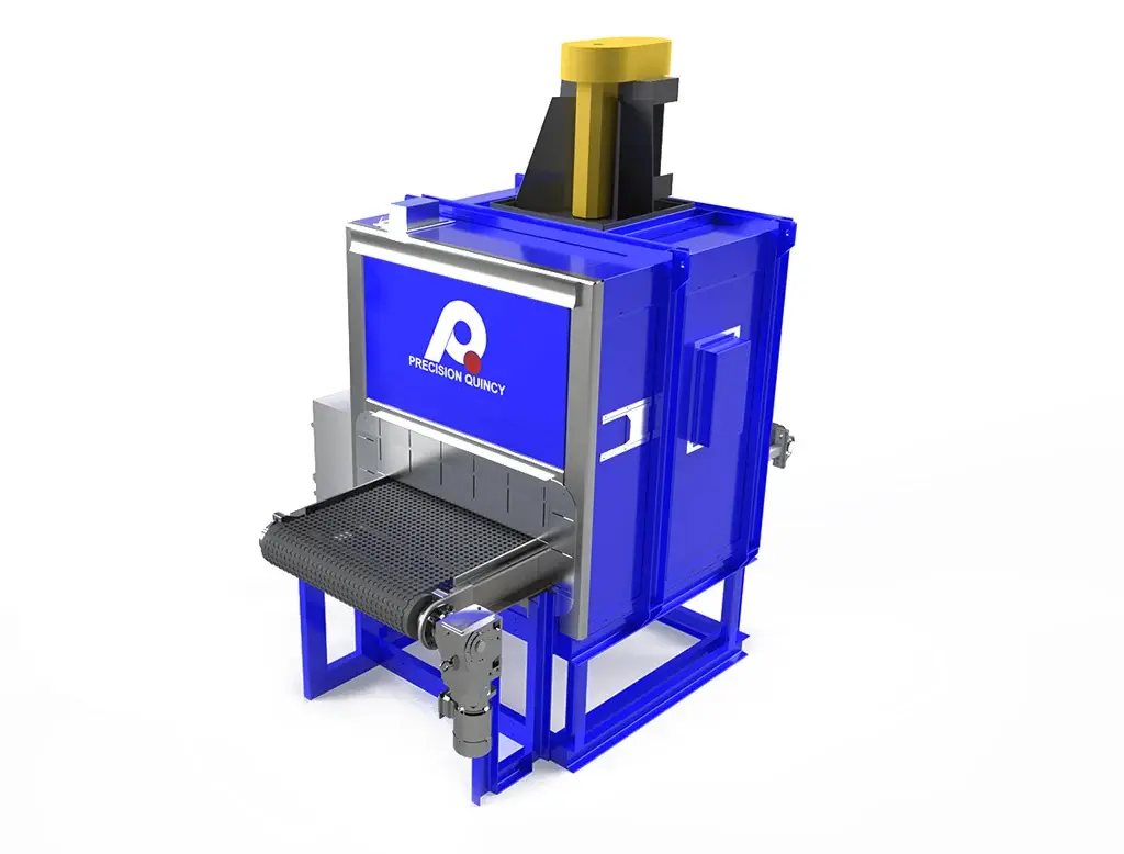
Dual-Zone Continuous Curing Oven for High-Volume Trim Finishing


Overview
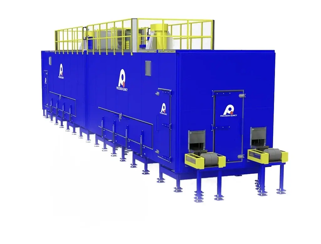
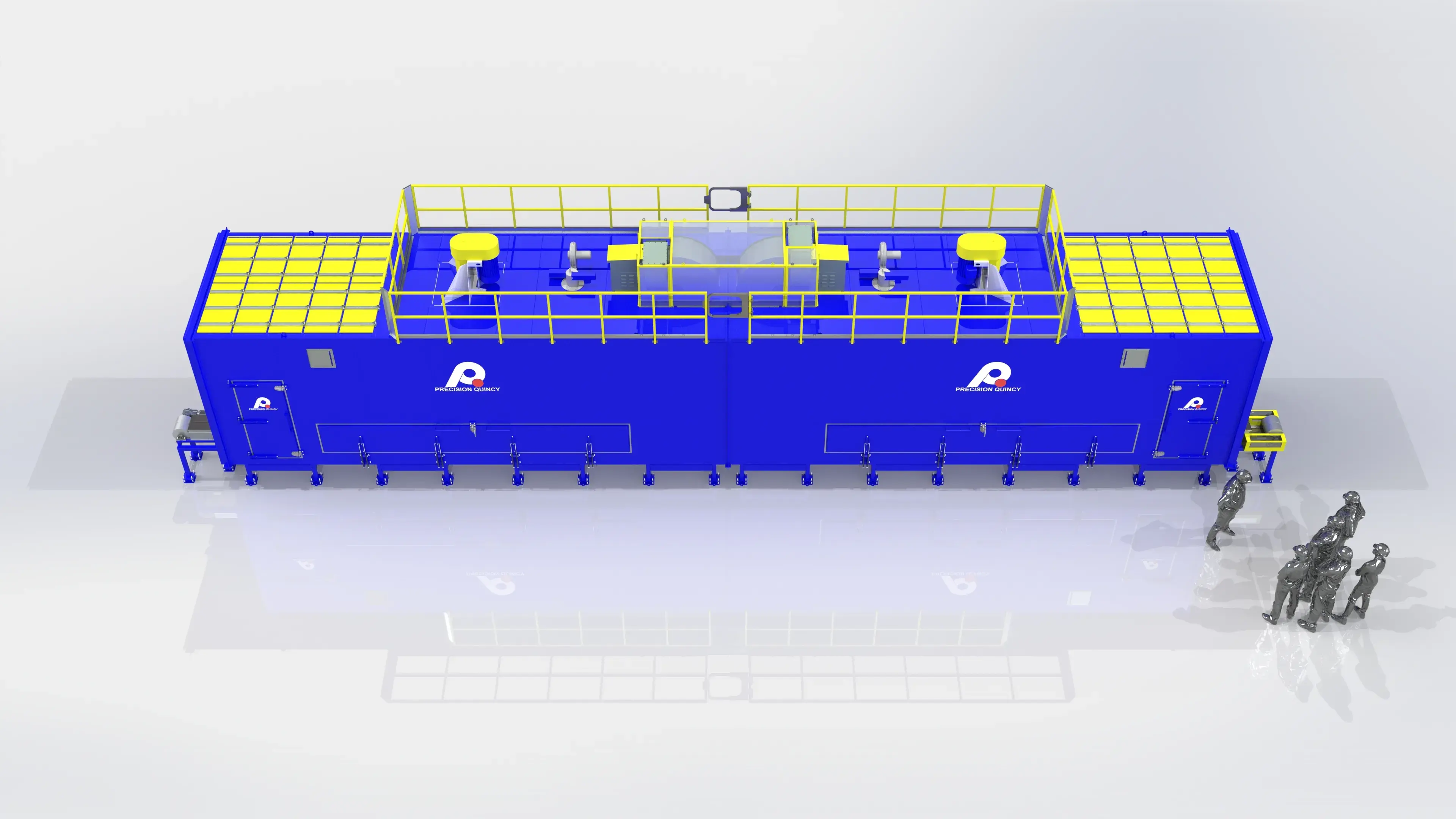
Precision Quincy engineered a high-throughput, dual-path curing module for a major North American buildingproducts manufacturer, designed to integrate inline within a two-machine production cell. The system cures edge-applied coatings on lengthwise-oriented trim boards—focusing heat where it matters (the edges) without wasting energy on wrapped top/bottom surfaces—while delivering approximately 152,000 lb/hr across a wide product mix.
To meet the customer’s requirements and belt limitations, the curing process was developed through a combination of Precision Quincy testing, customer experience, and prior application knowledge, resulting in a 212°F operating process with 450°F maximum capability for future flexibility. The final architecture uses two independently controlled zones and two side-by-side conveyor paths with fixed spacing to match the customer’s layout, combining edge-focused vertical-down airflow (5,800 FPM ±870 through 3/8″ slots), modulating exhaust (5,250–17,200 CFM) for stable low-temperature operation under low-NOx constraints, and a robust service-forward mechanical layout with central walk-through access.
A major North American building-products manufacturer required a continuous curing module to be integrated inline as part of a larger, two-machine production cell (the curing system mechanically and controls-wise interfaces with upstream/downstream equipment).
MATERIAL FLOW & LAYOUT
- Product travels lengthwise (boards oriented parallel to direction of travel; "skinny way in").
- Two parallel product paths run through the curing system.
- The customer required a specific fixed center-to-center spacing between the two paths to match their production layout.
THROUGHPUT REQUIREMENT (PRIMARY)
- The key requirement was mass throughput (≈152,000 lb/hr target). Line speed is secondary and is simply whatever speed is required to achieve lb/hr given product mix.
PRODUCT + UPSTREAM CONTEXT
- Trim boards are wood/composite.
- Upstream, the trim is wrapped on the top and bottom surfaces.
- After trim is cut, the exposed edges must be painted; this system's job is to dry/cure the edge paint.
ENERGY FOCUS / EDGE-ONLY HEATING CHALLENGE
- The customer's process requires concentrating heat transfer on the edges without wasting energy heating surfaces that do not need it.
- The system must accommodate a wide product width range (~1.5 in to 12 in) while still directing airflow/heat where needed (edge-focused) without disturbing product.
CONVEYOR/BELT REQUIREMENT + BELT TEMPERATURE CONSTRAINT
- The customer required a specific belt standard.
- The belt is not rated for the oven's maximum design temperature.
- Although the equipment is configured for up to 450°F max, the customer operates to keep the belt around ~212°F.
- A belt return/vestibule region is maintained cooler (as needed) to help protect the belt while still supporting production throughput.
LOW-NOX BURNER CORPORATE STANDARD
- The customer requires low-NOx burners.
- This creates a control/turndown challenge, especially at low heat-load conditions (e.g., empty/lightly loaded operation) where it is difficult to maintain low temperatures while preserving needed high-temperature capability.
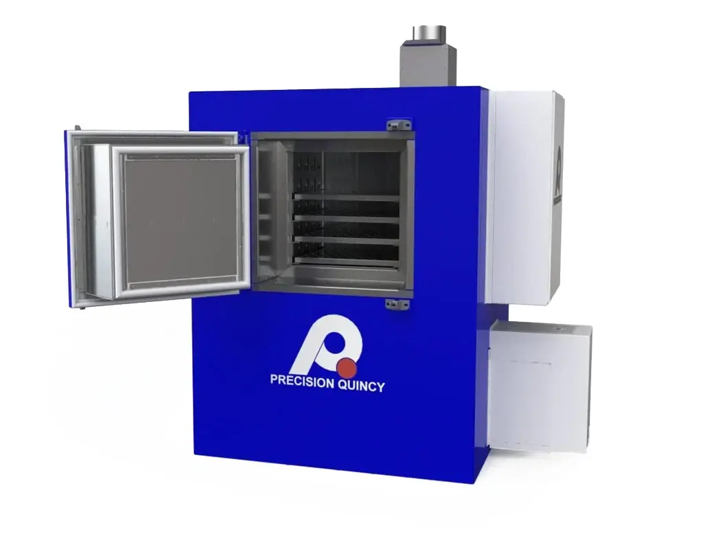
ACCESS / MAINTAINABILITY REQUIREMENT
- The customer required side access so operators can quickly remove broken boards inside the oven (open side access rather than full disassembly).
PRODUCT STABILITY REQUIREMENT
- Boards must remain stable and properly guided—no lateral drift, hopping, or airflow-induced movement—while still achieving the required edge paint cure.
FOOTPRINT CONSTRAINT
- The customer provided a very limited installation envelope; the full solution had to fit within ~800 inches total length.
These thermal process requirements were jointly developed to meet the customer's process needs, based on a combination of Precision Quincy testing, customer experience, and Precision Quincy's prior experience with similar product lines.
TEMPERATURE REQUIREMENTS
- Normal operating temperature: 212°F.
- Maximum capability: 450°F (future flexibility for product line changes; may require belt retrofit).
CONVEYOR EXPOSURE / TIME-IN-HEAT
- Conveyor speed must be adjustable to achieve different time-in-heat values based on product size.
- Speed range includes up to ~350 ft/min.
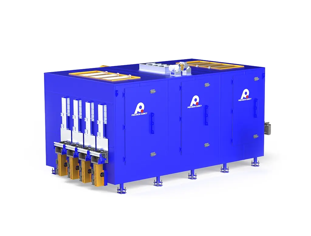
EDGE-FOCUSED AIRFLOW DELIVERY
- Airflow must be delivered vertically downward at the board edges.
- Target nozzle discharge velocity: 5,800 FPM, with allowable variation ±870 FPM.
- Nozzle geometry: 3/8-inch-wide slots.
EXHAUST REQUIREMENTS (TEMPERATURE CONTROL + PROCESS REMOVAL)
- Minimum exhaust: 5,250 CFM (water removal from drying + products of combustion).
- Maximum exhaust capability: 17,200 CFM to support stable low-temperature operation given low-NOx turndown limitations.
HEAT INPUT REQUIREMENT
- Required heat input: 5,000,000 BTU/hr.
MOISTURE LOAD
- Maximum water load capacity: 8 gallons/hr.
TEMPERATURE UNIFORMITY
- ±10°F from setpoint at the nozzle discharge (sufficient to meet even-heating requirement)
To deliver the thermal process requirements (which deliver the customer process requirements), Precision Quincy settled on the following equipment concept and architecture.
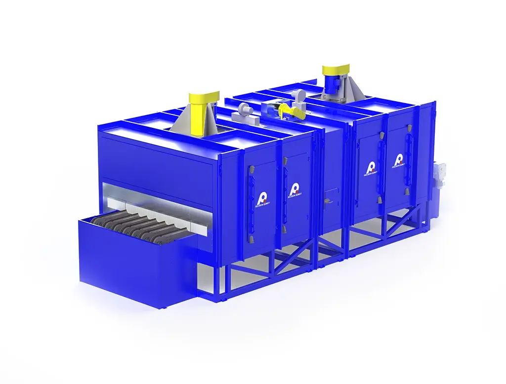
OVERALL CONCEPT
- Two-zone, dual-path conveyor oven.
- Top-mounted recirculation with burners located upstream of each recirculation fan.
- Conditioned air is directed down from nozzles above each conveyor, then returns down the sides back to the heat source/fan loop.
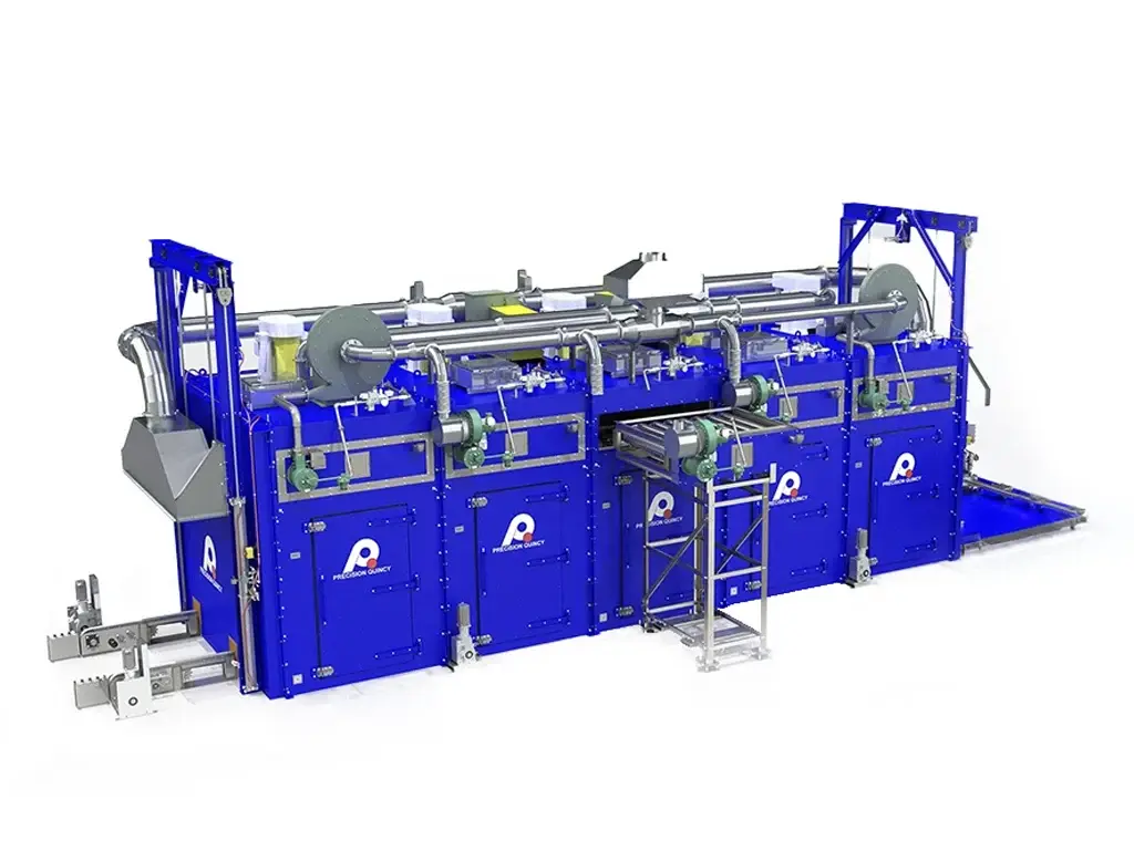
AIRFLOW/DUCTING ARCHITECTURE
- Return air flows back to a heat source located upstream of the recirculation fan.
- The recirculation fan pressurizes a duct with outlets to each side, feeding a supply plenum directly over each conveyor.
- Nozzles above each conveyor deliver the required edge-focused vertical-down airflow.
ZONE ARCHITECTURE (ONE FAN + ONE BURNER PER ZONE)
- Recirculation fan: 40-inch fan, 33,000 CFM @ 3 in. w.c. (concept-point), 25 HP motor (selected via fan curve analysis).
- Heating: Burners fire into a diffuser that mixes burner heat with incoming return air prior to fan pressurization. (2) Maxon OvenPak LE25 burners (one per zone), each 2.5 MMBtu/hr (5.0 MMBtu/hr total). SmartLink MRV servo-driven emissions control (NOx <30 ppm).
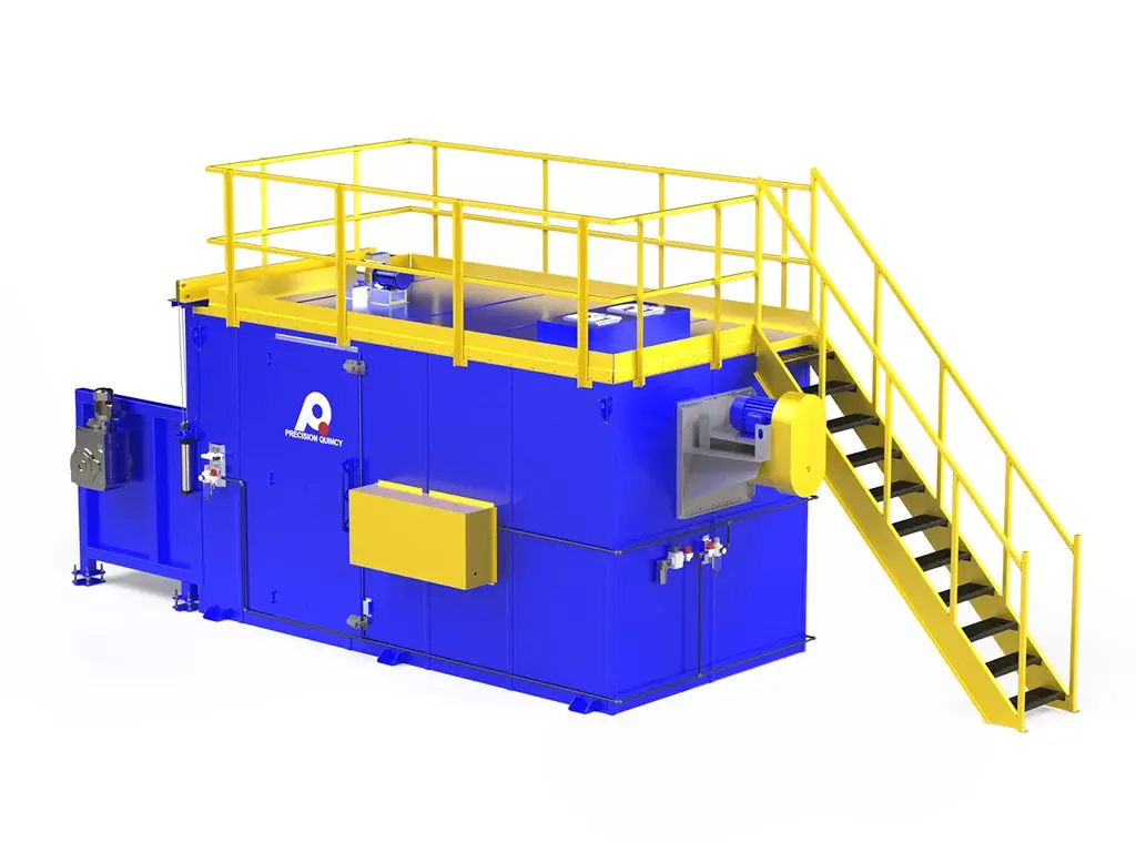
EXHAUST CONCEPT
- Exhaust system located at the center of the oven.
- Equipped with modulating dampers to support the required exhaust turndown/capability.
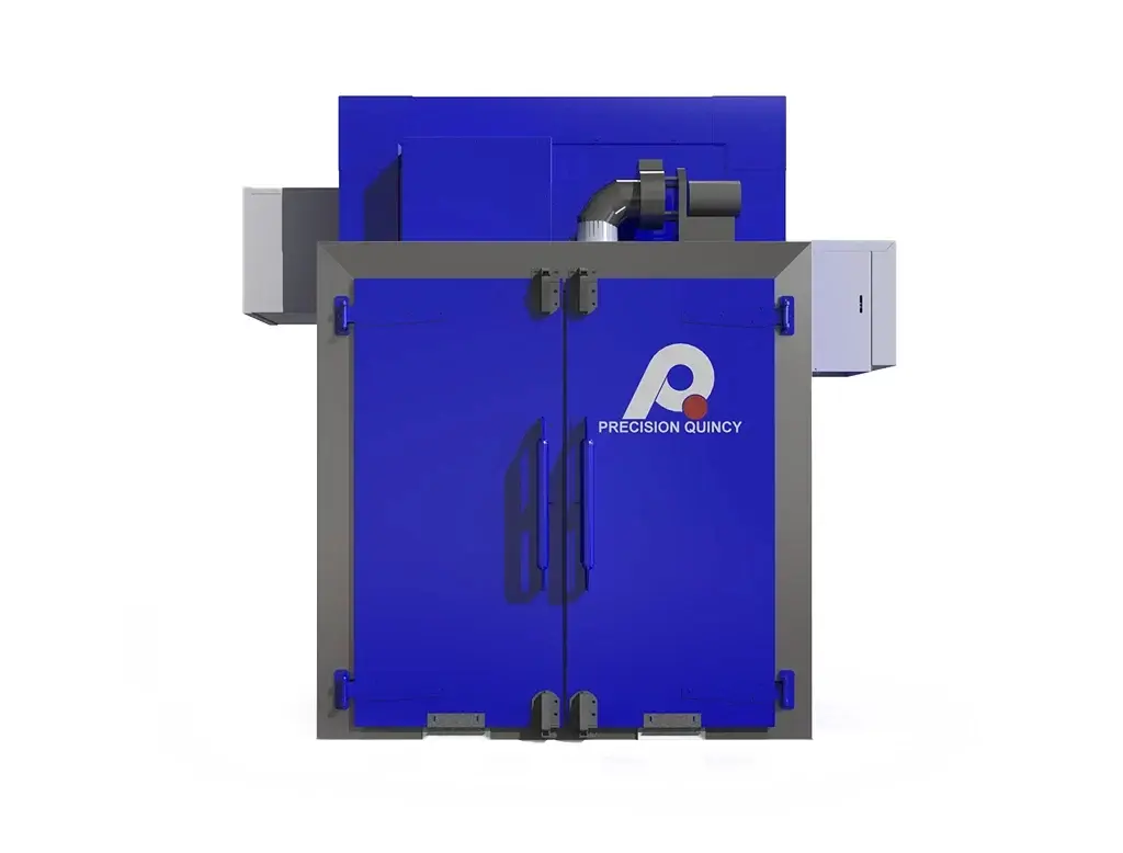
SERVICEABILITY / ACCESS
- Two independently operable conveyors run side-by-side with a central walk-through pathway for service.
- The center pathway also serves as part of the return-air space.
- Explosion relief incorporated, with as much relief area as practical placed in the roof.
- Total of 10 access doors. Large side access openings supported by an overhead truss concept enabled by the shell architecture.
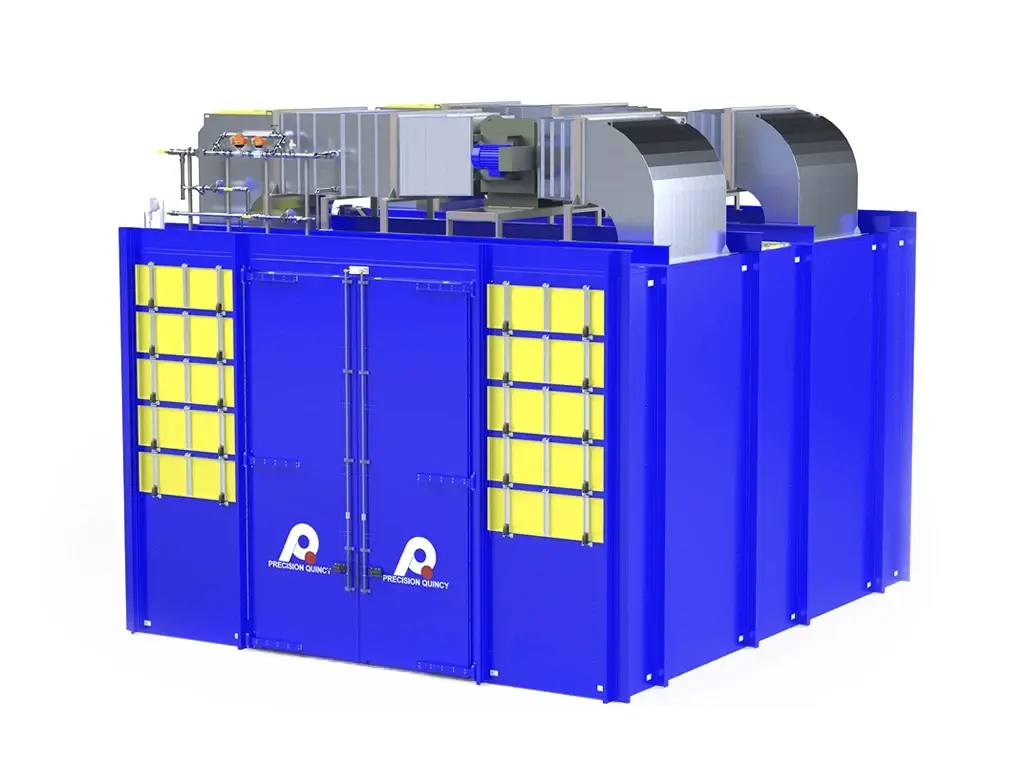
SHELL / STRUCTURAL ARCHITECTURE
- Shell built around a structural steel frame that integrates the conveyor support structure.
- Interior construction uses free-floating sheet-metal pans designed to accommodate thermal expansion/contraction while minimizing through-metal.
- Construction: 16-gauge interior pans (aluminized), insulation outside the interior pans, 16-gauge exterior cladding (mild steel), two-part epoxy paint, light gray specified by the customer.
SHIPPING ARCHITECTURE
- The oven ships as two main pieces (two zones).
- Full assembly supported on bolt-on stands removed for shipment to maintain legal over-the-road shipping height.
CONVEYOR / MECHANICAL CONCEPT HIGHLIGHTS
- Belt return runs through a vestibule and can be configured for additional cooling air (if needed) to protect the belt.
- Belt tracking uses a V-guide / V-groove on the back of the belt (no active tracking system).
- Drive: Each conveyor has its own gearbox on a torque arm. Drive motor: 2 HP per conveyor, VFD-controlled. Lag pulleys used to grip/drive the belt.
- Take-up: Rack-and-pinion synchronized take-up with pneumatic cylinders (one system per conveyor/zone). Bearing blocks on slides maintain pulley shaft alignment.
CONTROLS ARCHITECTURE
- Controls are remotely located.
- Allen-Bradley CompactLogix PLC controls this curing module and the adjacent paired equipment.
- VFDs are Yaskawa (customer-specified).
- Burner safety hardware uses a Karl Dungs-based safety system with Maxon/Honeywell burner control components.
OTHER NOTED ATTRIBUTES
- Coating is non-VOC.
- Roof areas not occupied by explosion relief are outfitted with guard rails for service access.
- Equipment was fully tested and accepted via FAT at Precision Quincy; a future widening retrofit was requested by the customer but has not been executed.
| OVEN CONFIGURATION | |
|---|---|
| Type | Continuous conveyor, two-zone, dual-path, vertical-down edge-focused airflow |
| Heated zone length (per zone) | 366 in (total: 732 in) |
| Width (per conveyor path) | 12 in |
| Clear height above belt | 5.5 in |
| Equipment overall dimensions | 186.9 in W × 800 in L × 189.5 in H |
| Inlet/outlet vestibules | 18 in each end |
| Overall length / shipping | ~60 ft total; shipped as (2) ~30 ft zone sections bolted together |
| Footprint constraint | Must fit within ~800 in total length installation envelope |
| Service access | Central walk-through pathway + side access; 10 access doors total |
| Explosion relief | Roof-mounted relief where practical; roof guard rails for access |
| THERMAL HEAT POWER SYSTEM | |
|---|---|
| Operating temperature | 212°F |
| Maximum temperature | 450°F (future flexibility; may require belt retrofit) |
| Temperature uniformity | ±10°F from setpoint at nozzle discharge |
| Heating zones | 2 |
| Heat source | (2) Maxon OvenPak LE25, 2.5 MMBtu/hr each (one per zone) |
| Heat power | 5,000,000 BTU/hr |
| Emissions control | Servo-driven SmartLink MRV (Maxon/Honeywell), mapped to maintain NOx < 30 ppm |
| RECIRCULATION / AIRFLOW SYSTEM | |
|---|---|
| Airflow pattern | Vertical-down, edge-focused discharge from overhead nozzles; side returns to heat source/fan |
| Nozzle geometry | 3/8 in wide slots |
| Nozzle discharge velocity | 5,800 FPM ±870 FPM |
| Fans (per zone) | 40 in fan; 33,000 CFM @ 3 in. w.c. (concept point) |
| Fan motor (per zone) | 25 HP |
| Burner location | Upstream of fan, firing into a diffuser for mixing prior to fan pressurization |
| EXHAUST SYSTEM | |
|---|---|
| Location | Center of oven |
| Minimum exhaust | 5,250 CFM |
| Maximum exhaust capability | 17,200 CFM |
| Control | Modulating dampers |
| Basis | Supports low-temperature stability with low-NOx turndown limits; removes water from drying + products of combustion |
| CONVEYOR / HANDLING SYSTEM | |
|---|---|
| Configuration | Two independently operable side-by-side conveyors (dual-path) |
| Drive (per conveyor) | 2 HP motor with gearbox on torque arm, VFD-controlled |
| VFDs | Yaskawa (customer specified) |
| Take-up | Rack-and-pinion synchronized take-up with pneumatic cylinders; bearing blocks on slides |
| Tracking | V-guide / V-groove on belt back (no active tracking system) |
| Drive interface | Lag pulleys for belt grip |
| Belt return | Return runs through vestibule; can be configured for additional cooling air if required |
| Conveyor capacity | 300 lb evenly distributed per conveyor |
| CONSTRUCTION MATERIALS / FINISH | |
|---|---|
| Primary structure | Structural steel frame integrating conveyor supports |
| Interior | 16-gauge aluminized free-floating pans (expansion/contraction tolerant) |
| Exterior | 16-gauge mild steel cladding |
| Paint | Customer-specified light gray, two-part epoxy coating |
| Thermal isolation | Insulation outside interior pans; minimized through-metal architecture |
| SAFETY & COMPLIANCE (BURNER / SYSTEM) | |
|---|---|
| NFPA 86 classification | Class A |
| Burner safety hardware | Karl Dungs-based safety system |
| Burner controls | Maxon/Honeywell components |
| CONTROLS & ELECTRICAL | |
|---|---|
| PLC | Allen-Bradley CompactLogix (controls this module + adjacent paired equipment) |
| Control cabinet location | Remotely located |
| PROCESS NOTES | |
|---|---|
| Coating | Non-VOC |
| Testing | Equipment completed FAT at Precision Quincy; customer accepted |
| Future | Customer requested a widening retrofit concept (not executed yet) |
