
Project Number: 5539
Dual-Zone Electric Composite Curing Oven for Space Launch Vehicle Composite Components
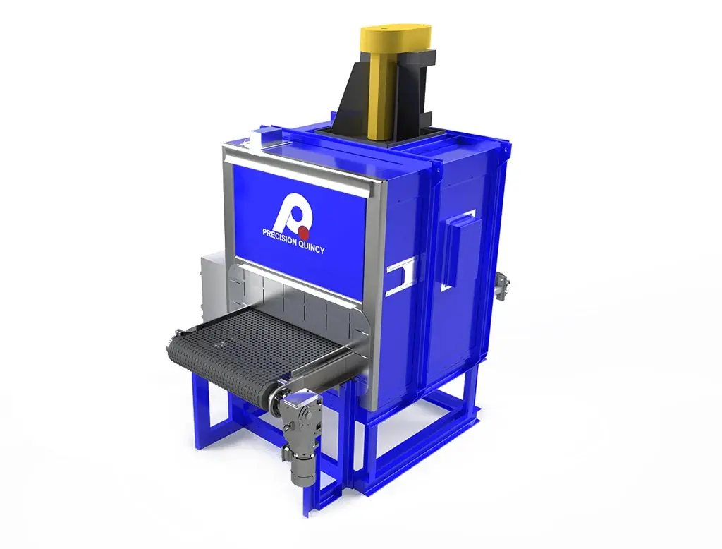
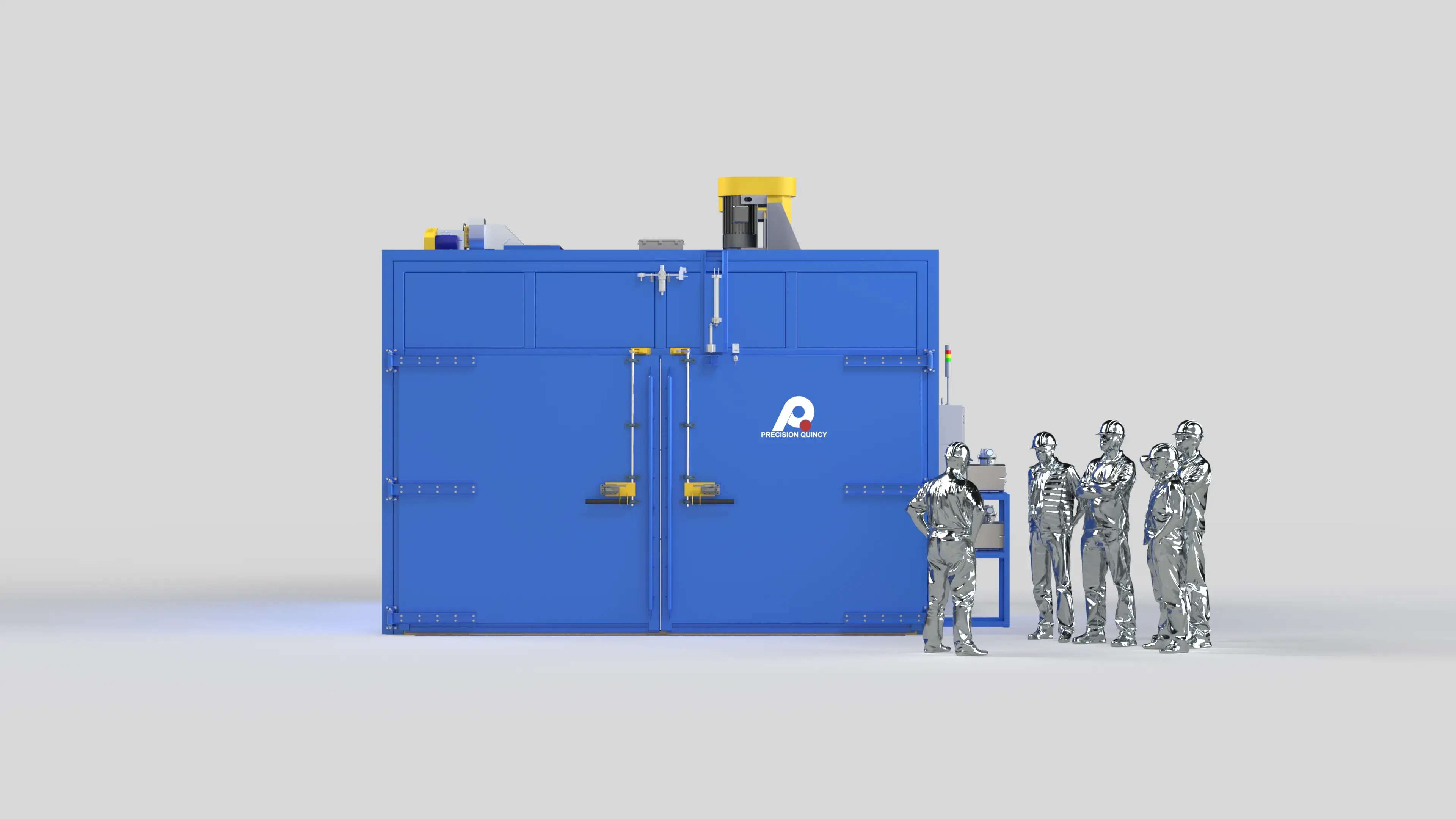
Dual-zone electrically heated Class B composite curing oven for vacuum-bagged space launch vehicle reinforcement components—198 kW total, 32,220 CFM recirculation, part-responsive cascade control, and integrated redundant vacuum support.
.webp?width=1400&name=5539%20UNITED%20LAUNCH%20(2).webp)
.webp?width=1400&name=5539%20UNITED%20LAUNCH%20(3).webp)
.webp?width=1400&name=5539%20UNITED%20LAUNCH%20(4).webp)
.webp?width=1400&name=5539%20UNITED%20LAUNCH%20(5).webp)
.webp?width=1400&name=5539%20UNITED%20LAUNCH%20(6).webp)
.webp?width=1400&name=5539%20UNITED%20LAUNCH%20(7).webp)
.webp?width=1400&name=5539%20UNITED%20LAUNCH%20(8).webp)
.webp?width=1400&name=5539%20UNITED%20LAUNCH%20(9).webp)
.webp?width=1400&name=5539%20UNITED%20LAUNCH%20(10).webp)
Overview
A high-temperature composite curing oven was engineered for composite reinforcement components used in space launch vehicle applications. The system needed to support large mold-based processing, pass-through cart movement, integrated vacuum functionality, and a tightly controlled electrically heated curing environment sized around the customer's tooling and production workflow.
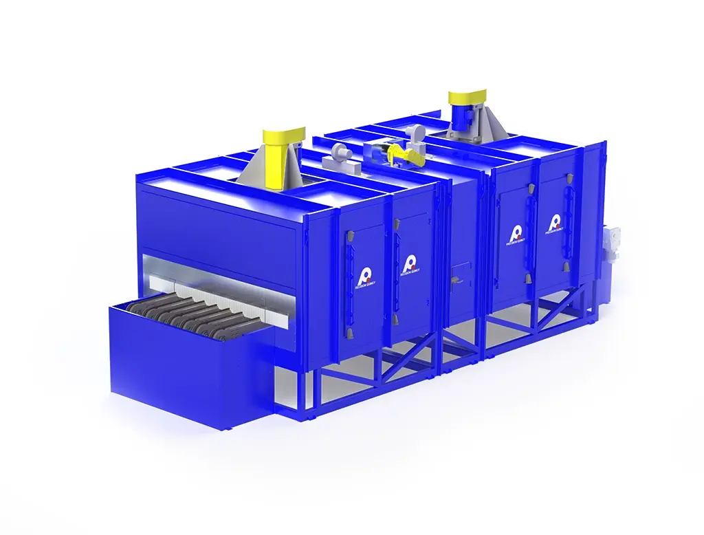
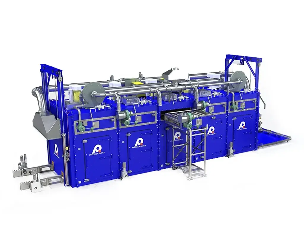
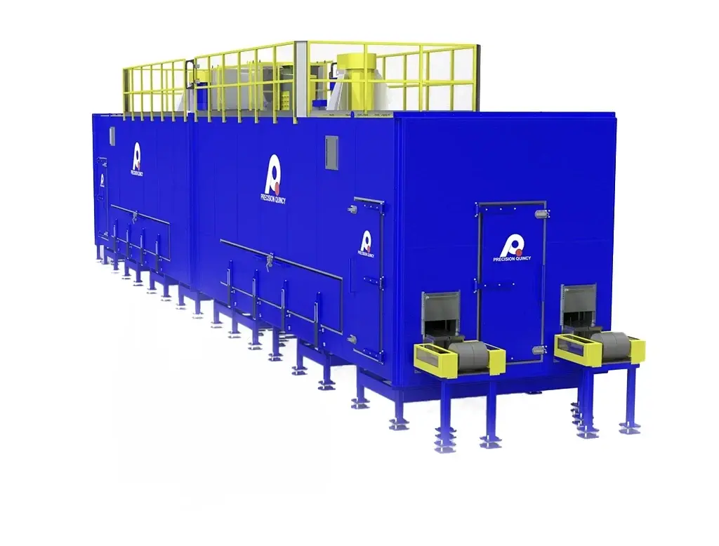
The solution was a dual-zone tunnel-style electric oven configured for two mold positions, with full horizontal airflow, direct cart duct connection capability, an insulated pit floor, AvPro-based process controls, and redundant vacuum support integrated into the curing workflow. The concept was built around the customer's mold and cart geometry while refining the airflow, controls, and service architecture into a production-capable, maintainable system.
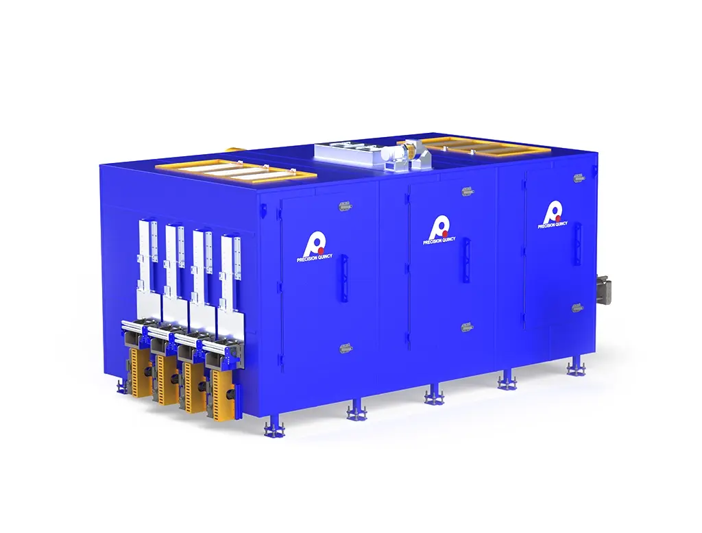
One of the most distinctive architectural elements was the direct cart duct interface. The supply duct system incorporated large round quarter-turn J-lock interface points along the lower side of the oven, allowing flexible hose connection from the oven supply duct directly into the customer's cart and mold assembly. When not in use, each interface point was closed with a plug assembly incorporating standard supply nozzles to maintain controlled airflow. The project was completed as a turnkey installation including startup, operator training, and UL field inspection and labeling at the installation site.
The process requirement was to cure composite reinforcement components for space launch vehicle applications. The process centered on loading large molds on wheeled carts and moving them longitudinally through the oven, driving the requirement for a tunnel-style configuration with pass-through access and a work envelope sized around the mold package.
APPLICATION REQUIREMENT
- Heated air supplied into the cart/mold assembly was used to heat the mold rather than directly impinge on the product; the product heated through the mold and the surrounding thermal environment.
- The oven was configured for two mold positions within the same system. Stated dimensional targets: approximately 13.1 ft usable width, 15 ft usable length, and 8.2 ft usable height.
- The process basis required accommodation of heavy tooling — molds on wheeled carts with floor loading capability up to 2,650 lb distributed across four 2 in. × 2 in. contact areas.
CART DUCT INTERFACE REQUIREMENT
- The oven supply system was required to connect via flexible ducting to the customer's cart and mold assembly, directing heated air into the mold/cart arrangement as part of the curing approach.
- Heated air supplied into the cart/mold assembly was used to heat the mold rather than directly impinge on the product; the product heated through the mold and the surrounding thermal environment.
PROCESS HANDLING REQUIREMENTS
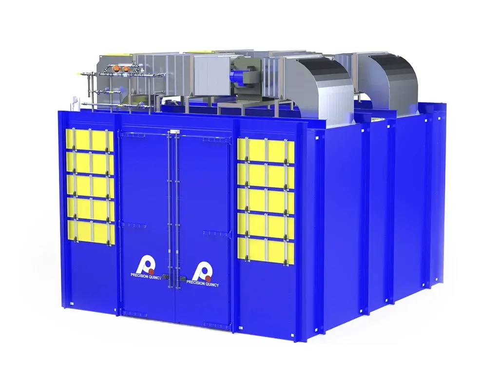
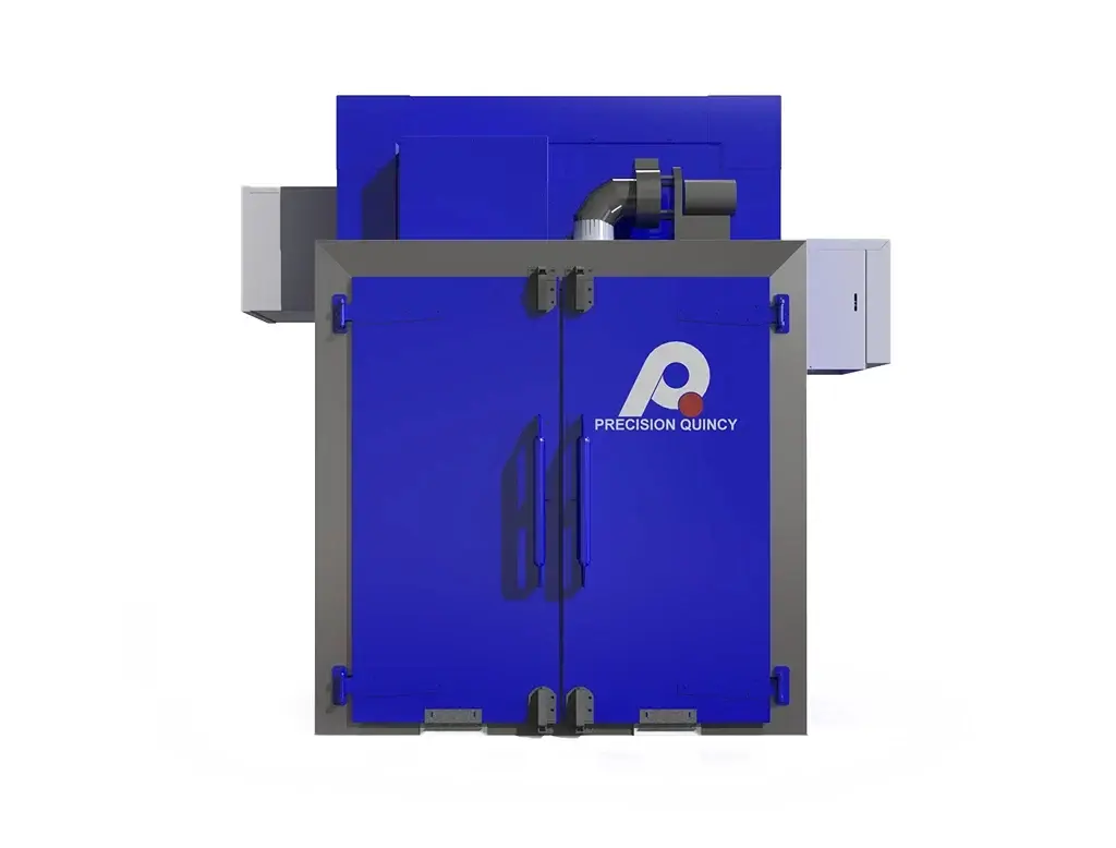
- Pass-through longitudinal cart loading was required, with bi-parting doors on both ends of the oven.
- Oven lighting and a door access strategy restricting outside access when part temperatures were above 40°C were required.
- The oven was required to be completely free of silicone in any form.
VACUUM / CONTAINMENT REQUIREMENT
- Integrated vacuum support was required for the vacuum-bagged product, with the thermal cycle and vacuum behavior working together as part of the cure sequence.
- Redundant vacuum pump backup was required and controlled through the HMI.
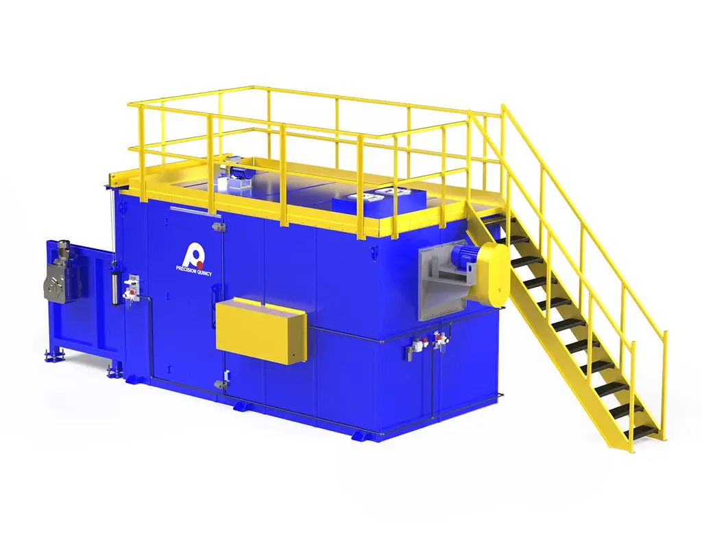
FOUNDATION / THERMAL ISOLATION REQUIREMENT
- The oven floor/foundation interface was required to remain thermally isolated such that the supporting foundation would not exceed 80°C.
- This drove a pit-installed insulated floor system with thermally decoupled construction and expansion accommodation.
UTILITY / INSTALLATION REQUIREMENT
- Required electrical service: 480V / 3PH / 60Hz.
- Required pneumatic supply for door locking: 80 PSI plant air.
- The project was completed as a turnkey installation with startup, training, and UL field inspection and labeling at the installation site.
The thermal process requirements were established around part-controlled composite curing for space launch vehicle reinforcement components, with acceptance criteria defined at the part rather than only at the oven air.
TEMPERATURE CAPABILITY
- Typical operating / process temperature: 392°F (200°C). Maximum part temperature: 464°F (240°C).
- Air uniformity target: ±10°F.
PART-TEMPERATURE ACCEPTANCE CRITERIA
- During heat-up and cooling phases: part temperature required to remain no more than 5°C above the desired rate/target condition and no more than 15°C below it.
- During dwell phases: required part tolerance of ±5°C.
- These part-level requirements made part-responsive temperature control a central aspect of the thermal process strategy rather than relying on open-loop oven air control alone.
HEAT-UP RATE REQUIREMENT
- Loaded heat-up capability: up to 1°C per minute while processing approximately 2,000 kg of mold mass plus approximately 500 kg of composite parts.
HEAT INPUT REQUIREMENT
- Heat source: electric resistance heating. Element basis: 3 kW elements.
- Heat power: 99 kW per zone; 198 kW total across both zones.
- Two independently modulating heating zones operating toward the same overall cure profile.
AIRFLOW DELIVERY REQUIREMENTS
- Airflow pattern: full horizontal airflow.
- Recirculation fans: two New York Blower 27 in. PLR recirculation fans, one per zone — 16,110 CFM per zone; 32,220 CFM total at 3 in. w.c. Both fans VFD-controlled; 15 HP per zone; 30 HP total.
- Supply duct geometry: sidewall ductwork with round distribution nozzles and quarter-turn 10 in. J-lock cart-connection fittings for direct airflow connection to customer cart ducting.
EXHAUST / VENTILATION BASIS
- Exhaust: PQ15 exhauster sized at 920 CFM at 1.5 in. w.c.; 0.75 HP motor. Roof-mounted vertical exhaust outlet. Exhaust opening: 10 in. × 6 in.
- Oven classification: NFPA 86 Class B.
PROCESS CONTROL BASIS
- Part-responsive cascade-style control strategy: part temperatures monitored via eight selectable part thermocouple inputs and used to constrain air-side response, managing loaded thermal behavior through both ramping and dwell portions of the cure cycle.
- An uninterruptible power supply was included for the controls system to protect the cure cycle during power events.
To deliver the process requirements for this space launch vehicle composite curing application, the following equipment concept and architecture was developed.
OVERALL CONCEPT
- One dual-zone tunnel-style electric Class B composite curing oven configured for two mold positions, with bi-parting doors on both ends for longitudinal pass-through cart movement.
- Top-mounted heat chamber with full horizontal airflow, direct cart duct interface, pit-installed thermally isolated floor, integrated redundant vacuum support, and AvPro CSS400 PC-based process controls.
HEATING ARCHITECTURE
- Heat source: electric resistance heat. Total installed heat: 198 kW (99 kW per zone) from 3 kW elements.
- Two independently modulating heating zones operating toward the same overall cure profile, with part-responsive cascade control constraining air-side response based on part thermocouple feedback.
AIRFLOW / RECIRCULATION ARCHITECTURE
- Recirculation fans: two New York Blower 27 in. PLR fans — 16,110 CFM per zone; 32,220 CFM total at 3 in. w.c.; 15 HP each; both VFD-controlled.
- Supply duct: sidewall distribution with round nozzles. Eight selectable part thermocouple inputs used in recipe-based temperature control.
- Exhaust: PQ15 exhauster — 920 CFM at 1.5 in. w.c.; 0.75 HP motor; roof-mounted vertical outlet.
CART DUCT INTERFACE ARCHITECTURE
- Lower sidewall supply duct incorporates quarter-turn 10 in. bulkhead/J-lock interface points for flexible hose connection from the oven supply duct to the customer's cart/mold assembly.
- When a cart connection point is not in use, a nozzle-style plug-in closure maintains controlled airflow rather than allowing bleed through unused openings.
SHELL / FLOOR / CONSTRUCTION ARCHITECTURE
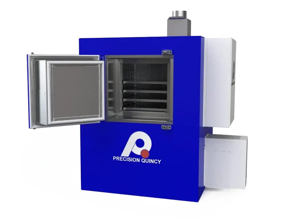
- Shell: tongue-and-groove insulated panel construction with structural steel reinforcement. 4 in. thick walls with 4 in. of 6 lb mineral wool insulation.
- Work area dimensions: 157.2 in. wide × 180 in. deep × 98.4 in. high. Overall dimensions: approximately 252.24 in. W × 217.44 in. D × 170.40 in. H.
- Floor: reinforced insulated pit floor sections with interlocking expansion-gap design for cart roll-over capability. Pit-installed to decouple the load surface thermally from the building foundation, keeping the foundation below 80°C.
- Interior: 18 ga aluminized steel, unpainted. Exterior: 18 ga aluminized steel, finished RAL 7035 light gray.
- Exterior: 18 ga aluminized steel, finished RAL 7035 light gray.
- Doors: light blue RAL 5012. Silicone-free construction throughout.
- Control panel: ANSI 61 gray.
- Silicone-free construction throughout.
VACUUM ARCHITECTURE
- Integrated redundant vacuum pump architecture controlled through the HMI for vacuum-bagged product processing.
- Vacuum support operates as part of the thermal cure sequence.
CONTROLS ARCHITECTURE
- Process controls: AvPro CSS400 PC-based system with AvPro I/O/PLC hardware; 10 in. HMI; eight selectable part thermocouple inputs for recipe-based temperature control.
- Controls features: two independently modulated zone controllers; two recirculation fan VFDs; dual zone high-limit controllers; redundant vacuum pump control; stack light; uninterruptible power supply for controls.
- Safety: internal E-stops on both side access areas; pneumatic door locking (80 PSI); E-stop logic shuts off heat and unlocks doors while recirculation/exhaust fans continue operating; work-area high-limit controllers for both zones.
- Applicable standards: NFPA 79, NFPA 86, UL 508A. UL field labeled at installation site.
| OVEN CONFIGURATION | |
|---|---|
| Type | Electrically heated dual-zone Class B composite curing oven |
| Application | Composite reinforcement component curing for space launch vehicle applications |
| Heated Zones | Two equal zones; approx. 90 in. each within 180 in. total work depth |
| Work Area Dimensions | 157.2 in. wide × 180 in. deep × 98.4 in. high |
| Overall Dimensions | Approx. 252.24 in. W × 217.44 in. D × 170.40 in. H |
| Door Configuration | Bi-parting doors on both ends; tunnel-style pass-through |
| Floor System | Pit-installed reinforced insulated floor with expansion-gap cart roll-over design; foundation kept below 80°C |
| Silicone | Silicone-free construction throughout |
| Installation Basis | Turnkey with startup, training, and UL field labeling at installation site |
| THERMAL HEAT POWER SYSTEM | |
|---|---|
| Operating Temperature | 392°F (200°C) typical |
| Maximum Temperature | 464°F (240°C) |
| Air Uniformity | ±10°F |
| Part Tolerance — Dwell | ±5°C |
| Part Tolerance — Ramp/Cool | No more than +5°C above / −15°C below target rate |
| Heat Source | Electric resistance heating elements (3 kW each) |
| Total Heat Power | 198 kW (99 kW per zone) |
| Zone Architecture | Two independently modulating zones toward the same cure profile |
| Heat Control Strategy | Part-responsive cascade control via eight selectable part thermocouple inputs |
| Oven Classification | NFPA 86 Class B |
| RECIRCULATION / AIRFLOW SYSTEM | |
|---|---|
| Airflow Pattern | Full horizontal airflow |
| Recirculation Fans | Two NYB 27 in. PLR plug fans (one per zone) |
| Recirculation Airflow | 16,110 CFM per zone; 32,220 CFM total at 3 in. w.c. |
| Fan Motors | 15 HP per zone; 30 HP total; both VFD-controlled |
| Supply Duct Geometry | Sidewall ductwork with round distribution nozzles |
| Cart Duct Interface | Quarter-turn 10 in. J-lock bulkhead fittings for direct flexible hose connection to customer cart/mold ducting; nozzle-style plug closures when not in use |
| Heat Chamber Location | Top-mounted |
| EXHAUST SYSTEM | |
|---|---|
| Exhaust Fan | PQ15 exhauster |
| Exhaust Airflow | 920 CFM at 1.5 in. w.c. |
| Fan Motor | 0.75 HP |
| Exhaust Outlet | Roof-mounted vertical; 10 in. × 6 in. exhaust opening |
| PRODUCT / CART HANDLING | |
|---|---|
| Loading Style | Batch cart / mold loading through tunnel oven with longitudinal pass-through access |
| Powered Conveyor | None; customer-provided wheeled carts |
| Floor Load Capacity | 2,650 lb on four 2 in. × 2 in. contact areas |
| Process Load Basis | Approx. 2,000 kg molds plus approx. 500 kg composite parts |
| Heat-Up Rate Basis | Up to 1°C per minute loaded |
| Cart Duct Connection | Customer cart connects to oven supply duct via 10 in. J-lock fittings and flexible hose |
| VACUUM SYSTEM | |
|---|---|
| Configuration | Integrated redundant vacuum pump architecture |
| Control | Vacuum support controlled through HMI; redundant pump backup |
| Process Integration | Vacuum and thermal cycle operate together as part of the cure sequence |
| CONSTRUCTION MATERIALS / FINISH | |
|---|---|
| Shell | Tongue-and-groove insulated panels with structural steel reinforcement |
| Wall Thickness | 4 in. with 4 in. of 6 lb mineral wool |
| Interior | 18 ga aluminized steel, unpainted |
| Exterior | 18 ga aluminized steel; RAL 7035 light gray |
| Door Finish | RAL 5012 light blue |
| Control Panel | ANSI 61 gray |
| Floor Construction | Reinforced insulated pit floor; interlocking expansion-gap design; unpainted mild steel surface |
| Silicone Content | None — silicone-free throughout |
| SAFETY & COMPLIANCE | |
|---|---|
| NFPA 86 Classification | Class B |
| Applicable Standards | NFPA 79, NFPA 86, UL 508A |
| UL Listing | UL field labeled at installation site |
| Door Safety | Pneumatic door locking (80 PSI); access restricted above 40°C part temperature |
| Internal E-Stops | Both side access areas; E-stop shuts off heat and unlocks doors while fans continue |
| High-Limit Protection | Dual zone work-area high-limit controllers |
| CONTROLS & ELECTRICAL | |
|---|---|
| Process Controls | AvPro CSS400 PC-based system with AvPro I/O/PLC hardware |
| HMI | 10 in. HMI |
| Part Thermocouple Inputs | Eight selectable part thermocouple inputs for recipe-based temperature control |
| Zone Control | Two independently modulating zone controllers |
| Vacuum Control | Redundant vacuum pump control through HMI |
| Fan Drives | Two recirculation fan VFDs |
| Power Protection | Uninterruptible power supply for controls |
| PQ Enclosure | NEMA 12 electrical enclosure adjacent to oven |
| AvPro Enclosure | Rolling NEMA 12 cart/mobile cabinet |
| Primary Power | 480V / 3PH / 60Hz |
| Pneumatic Supply | 80 PSI for door locking |
| Panel Listing | UL 508A Open Industrial Control Panel |
| PROCESS SUMMARY | |
|---|---|
| Product | Vacuum-bagged composite reinforcement components for space launch vehicle applications |
| Market / Application | Aerospace — space launch vehicle manufacturing |
| Process Type | Dual-zone part-responsive composite curing with integrated vacuum support |
| Cure Basis | Product heated through mold and surrounding thermal environment; not direct air impingement on product |
| Testing / Validation | Pre-assembly, pre-wiring, pre-test at operating and maximum rated temperature, and multi-point uniformity testing prior to shipment; turnkey installation with startup, training, and UL field labeling |
| Key Verification | Part-level temperature control within ±5°C during dwell and −5°C/+15°C during ramp/cool, maintained across two independently modulated zones processing approximately 2,500 kg of mold and composite load |
