
Project Number: 5480
High Throughput Airbag Cap Foil Sealing Thermal Processing System for Automotive Safety Component Manufacturing
.webp?width=1400&name=5480%20AUTOLIV%20(2).webp)
.webp?width=1400&name=5480%20AUTOLIV%20(3).webp)
.webp?width=1400&name=5480%20AUTOLIV%20(4).webp)
.webp?width=1400&name=5480%20AUTOLIV%20(6).webp)
.webp?width=1400&name=5480%20AUTOLIV%20(7).webp)
.webp?width=1400&name=5480%20AUTOLIV%20(8).webp)
.webp?width=1400&name=5480%20AUTOLIV%20(9).webp)
.webp?width=1400&name=5480%20AUTOLIV%20(10).webp)

.webp?width=1400&name=5480%20AUTOLIV%20(12).webp)
Overview
A global automotive safety manufacturer required a high-throughput production solution for sealing airbag inflator caps used in automotive restraint systems. These caps contain pyrotechnic components and require a hermetic foil seal to prevent moisture intrusion that could degrade the explosive charge. Historically, the customer used thermal bonding to attach the foil membrane. When some competitors attempted to eliminate heat and rely solely on pressure to reduce manufacturing cost, large-scale safety recalls demonstrated that pressure-only bonding could allow moisture infiltration — resulting in catastrophic airbag failures in service.
Because of these failures, the customer retained the thermal bonding process and needed to rapidly scale global production to meet increased demand created by competitor recalls. Precision Quincy had previously delivered several high-throughput systems capable of meeting the required cycle time. For a new production facility in India, the customer required the same throughput performance — one completed part every four seconds — but in half the equipment footprint of earlier installations.
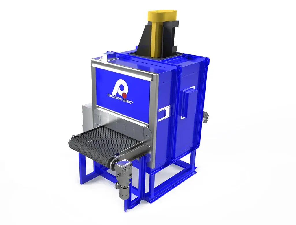
To meet this challenge, Precision Quincy redesigned the thermal processing system into a highly compact architecture with roof-mounted heating and cooling equipment, a high-density 435-station indexing conveyor at 4-inch station pitch, removable duct modules for service access, per-part tracking with automatic reject logic, and an acoustic-shrouded cooling section to maintain operator noise compliance — all within a footprint dramatically smaller than predecessor equipment while preserving sealing reliability and achieving full global component availability for the India installation.
The customer manufactures a cup-shaped metal component known as an airbag cap. A foil membrane must be thermally bonded to the inside of the cap to create a moisture-proof hermetic seal protecting the pyrotechnic inflator material. The thermal bonding process is safety-critical: moisture infiltration of the sealed cavity can degrade the explosive charge and result in airbag system failure in a crash event.
PROCESS OBJECTIVE
- Bond foil membrane to the inside surface of the airbag cap through controlled thermal processing.
- Maintain hermetic sealing reliability required for automotive safety components subject to stringent qualification and field performance requirements.
- Deliver extremely high production throughput to support rapidly scaled global demand.
THROUGHPUT REQUIREMENT
- Target production rate: 1 part every 4 seconds.
- Maximum throughput: approximately 900 parts per hour.
EQUIPMENT FOOTPRINT CONSTRAINT
- New system required to deliver equivalent throughput to existing Precision Quincy installations.
- Total equipment footprint limited to approximately half the size of earlier systems to fit the new India facility layout.
GLOBAL MANUFACTURING REQUIREMENT
- Equipment installed in a new customer production facility in India.
- System required to use components commercially available in India, including earlier-generation PLC hardware specifications.
- Packaging for breakbulk export shipment with vacuum shrink wrap and desiccant protection.
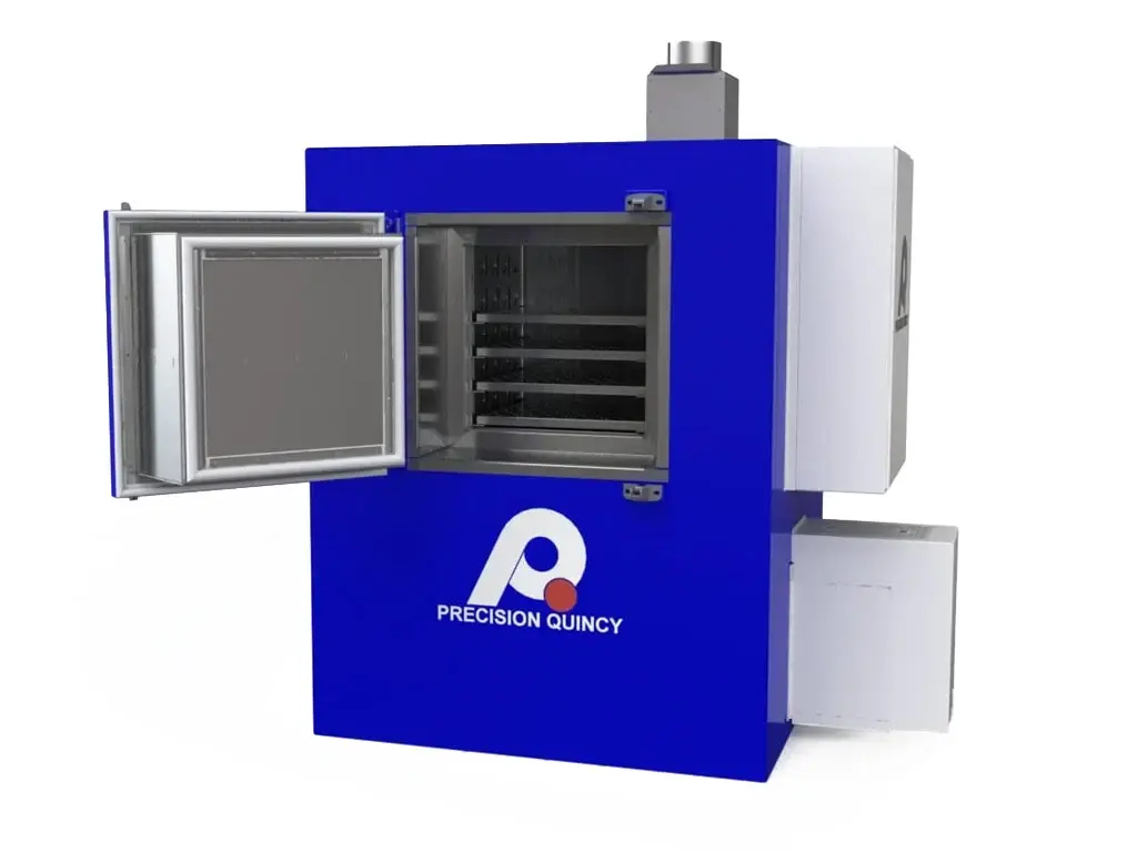
PART FORMING AND SEALING MECHANICS
- Each cap includes a foil membrane inserted prior to thermal processing.
- A rubber sealing element (“donut”) with cam actuation applies pressure during the thermal bonding cycle to form the foil seal.
- Tooling required to be quick-change without tools to support multiple part sizes. Spring detent mechanisms allow rapid replacement of sealing elements.
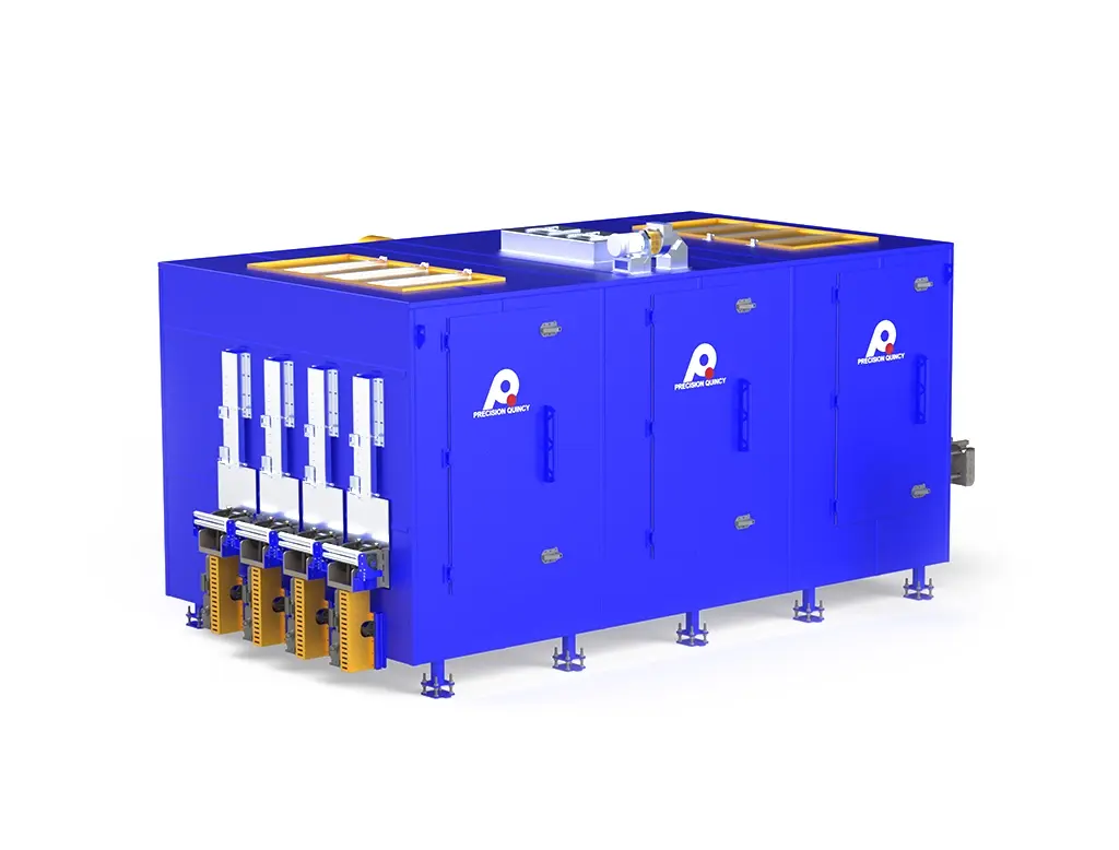
POST-PROCESS HANDLING AND PART TRACKING
- Parts must exit the system sufficiently cooled for downstream operator handling.
- Each part location is individually tracked throughout the oven process so the system can associate real-time process status with the specific part being unloaded.
- Parts are not accepted or rejected while still inside the machine; final pass/fail determination is made at the unload point.
- A red/green operator indicator identifies whether the unloaded part is acceptable or must be rejected. Rejected parts are directed into an integrated drop chute with photoeye confirmation before the next conveyor index is permitted.
NOISE, SAFETY, AND QUALIFICATION REQUIREMENTS
- Equipment designed to meet customer sound requirements at the operator station.
- System designed to comply with NFPA 86 internal design standards.
- Post-production qualification: an extended validation period of approximately three months is required before production release, during which a statistically meaningful quantity of parts is evaluated to confirm consistent sealing performance.
The thermal processing concept was based on previous successful installations developed by Precision Quincy for the customer. Testing demonstrated that high-velocity impingement airflow delivered vertically downward onto the caps provides the heat transfer rate required to reach sealing temperature within the available process time at the specified 4-second index interval.
AIRFLOW DELIVERY METHOD
- Vertical downward airflow delivered directly onto the tops of the caps.
- High-velocity nozzle discharge at approximately 4,000 FPM.
- Temperature uniformity: ±10°F measured at nozzle discharge across the heating zone.
PROCESSING ARCHITECTURE
- Total stations: 435 stations at 4-inch station pitch.
- Conveyor indexing interval: 4 seconds per index.
- This configuration enables approximately 900 parts/hour throughput while maintaining sufficient thermal dwell for reliable foil bonding.
THERMAL ZONES
- Ramp Zone: rapidly raises part temperature to bonding condition. Operating temperature 410°F; maximum capability 500°F; heating power 72 kW. Recirculation fan: 18 in. NYB PLR at 7,400 CFM, 7.5 HP.
- Soak Zone: maintains the required bonding temperature for the dwell period. Operating temperature 385°F; maximum capability 500°F; heating power 36 kW. Recirculation fans: (2) 18 in. NYB PLR at 14,800 CFM total, 15 HP.
- Cooling Zone: forced-air cooling reduces part temperature for safe downstream handling. Two vane-axial fans at 5,425 CFM each; two cooling coils at 52,950 BTU/hr each (105,900 BTU/hr total cooling capacity).
PROCESS MONITORING AND REJECT LOGIC
- Each heating zone contains approximately six air-temperature monitoring thermocouples that continuously verify the process environment remains within the validated temperature band.
- If any zone temperature deviates outside the acceptable range, the control system flags the specific part positions currently inside the affected zone.
- The part tracking system carries this status forward through the machine — affected parts are automatically rejected at the unload station without operator decision required.
- System monitors for both over-temperature and under-temperature conditions on a per-part-position basis.
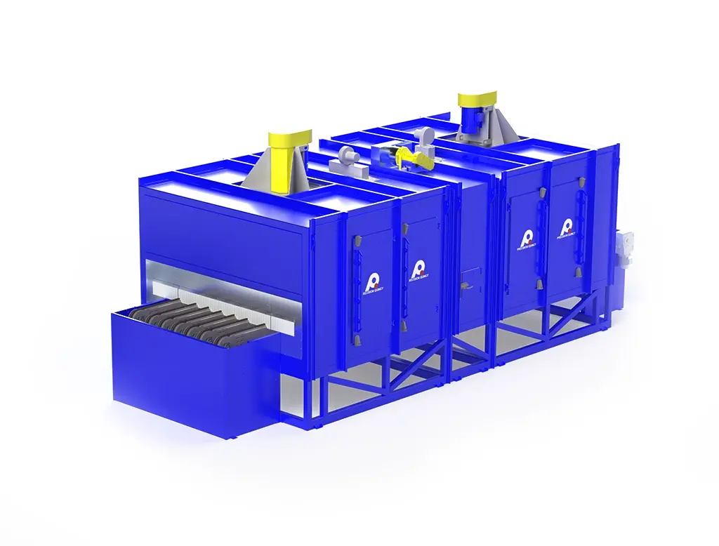
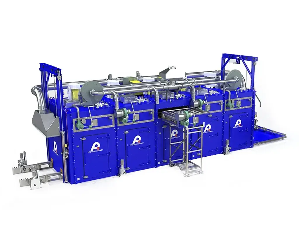
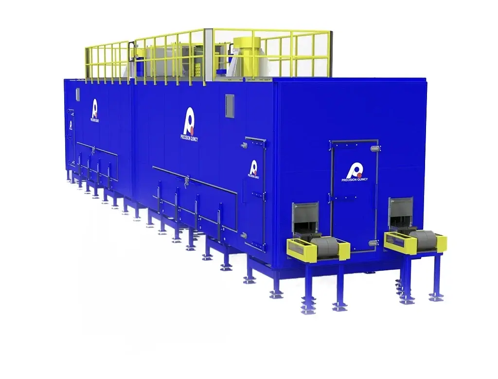
To deliver the required throughput within the reduced footprint, Precision Quincy developed a compact multi-zone thermal processing architecture in which all heating and cooling equipment is roof-mounted, freeing the lower machine envelope for the high-density conveyor and eliminating the side-mounted heat chamber space consumed by earlier equipment generations. The combination of roof-mounted systems, 4-inch station pitch, and a 435-station indexing path allowed the new design to achieve equivalent throughput in approximately half the floor space of predecessor installations.
OVERALL EQUIPMENT CONCEPT
- Compact multi-zone indexing thermal processing oven: Ramp Zone, Soak Zone, and integrated Cooling Zone.
- All heating and cooling equipment roof-mounted to minimize system footprint.
- Single-strand chain-on-edge conveyor with hollow-pin chain and oversized rollers, bolted cap carriers, and helical bevel gearbox drive.
- Equipment dimensions: 150.6 in. H × 190 in. W × 156 in. D (operating); 123.5 in. D shipping depth.
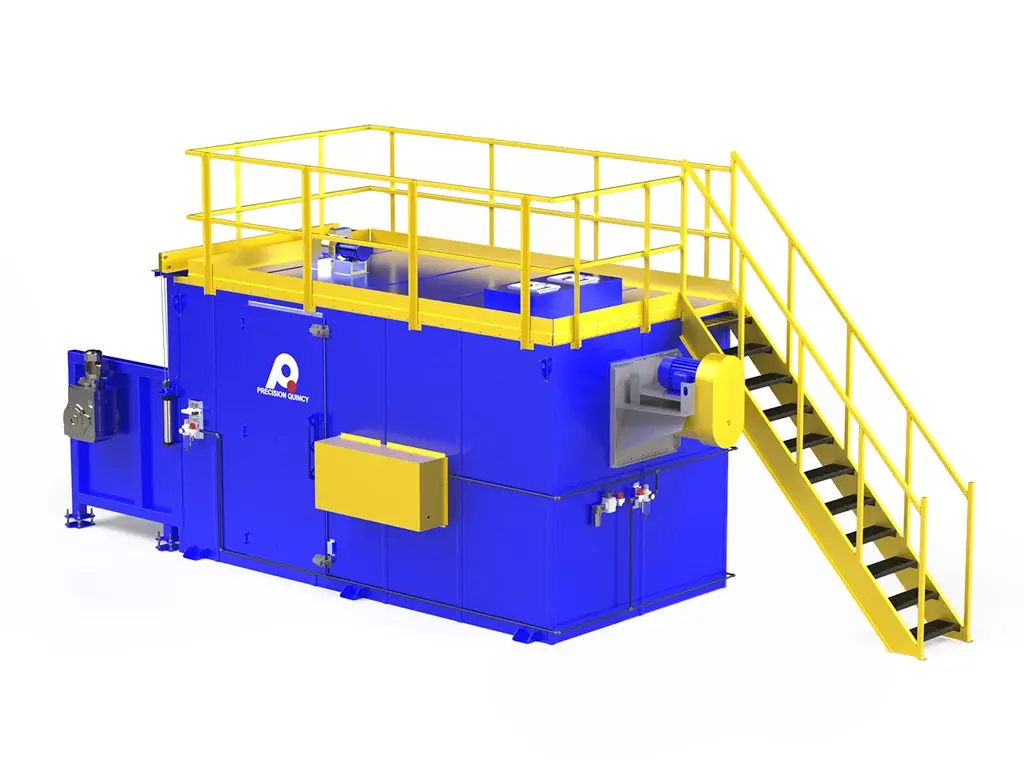
SERVICEABILITY ARCHITECTURE
- Due to the extremely compact design, internal service access is provided through a removable duct architecture: five sliding service doors on the non-load side allow duct modules to slide laterally out of the machine.
- This arrangement provides access to sprockets, chain components, and internal mechanisms without increasing the equipment footprint — functioning similarly to a magazine-style removable module system.
HEATING ARCHITECTURE
- Ramp Zone: 72 kW electric heating, 3 kW elements; 18 in. NYB PLR recirculation fan at 7,400 CFM, 7.5 HP; operating at 410°F, maximum 500°F.
- Soak Zone: 36 kW electric heating; (2) 18 in. NYB PLR recirculation fans at 14,800 CFM total, 15 HP; operating at 385°F, maximum 500°F.
- Heating section skins: 18-gauge aluminized steel. Shell: structural reinforced insulated panels, 15 in. wall thickness.
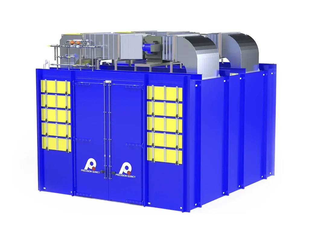
COOLING ARCHITECTURE
- Forced-air cooling section with (2) vane-axial fans at 5,425 CFM each and (2) cooling coils at 52,950 BTU/hr each — 105,900 BTU/hr total cooling capacity.
- Acoustic noise control: the compact machine layout places the cooling zone discharge near the operator station, requiring additional sound-reduction measures. The exit of the cooling zone is equipped with a foam-lined discharge tunnel and each cooling fan assembly is enclosed within an acoustic foam shroud to meet operator noise requirements.
- Cooling section construction: non-insulated aluminized steel (no thermal retention required).
CONTROLS AND PART TRACKING ARCHITECTURE
- PLC: Mitsubishi iQ-R R04CPU. Temperature control: WRM system.
- Two HMIs: primary operator HMI at the loading/unloading station; secondary HMI at the low-voltage control cabinet for maintenance and diagnostics.
- The control system tracks each part location through all 435 stations, associating real-time process status with each specific part position.
- At unload, a red/green visual indicator directs the operator to accept or reject the part. For rejected parts, a drop chute with integrated photoeye confirmation prevents the conveyor from indexing until the rejected part has cleared.
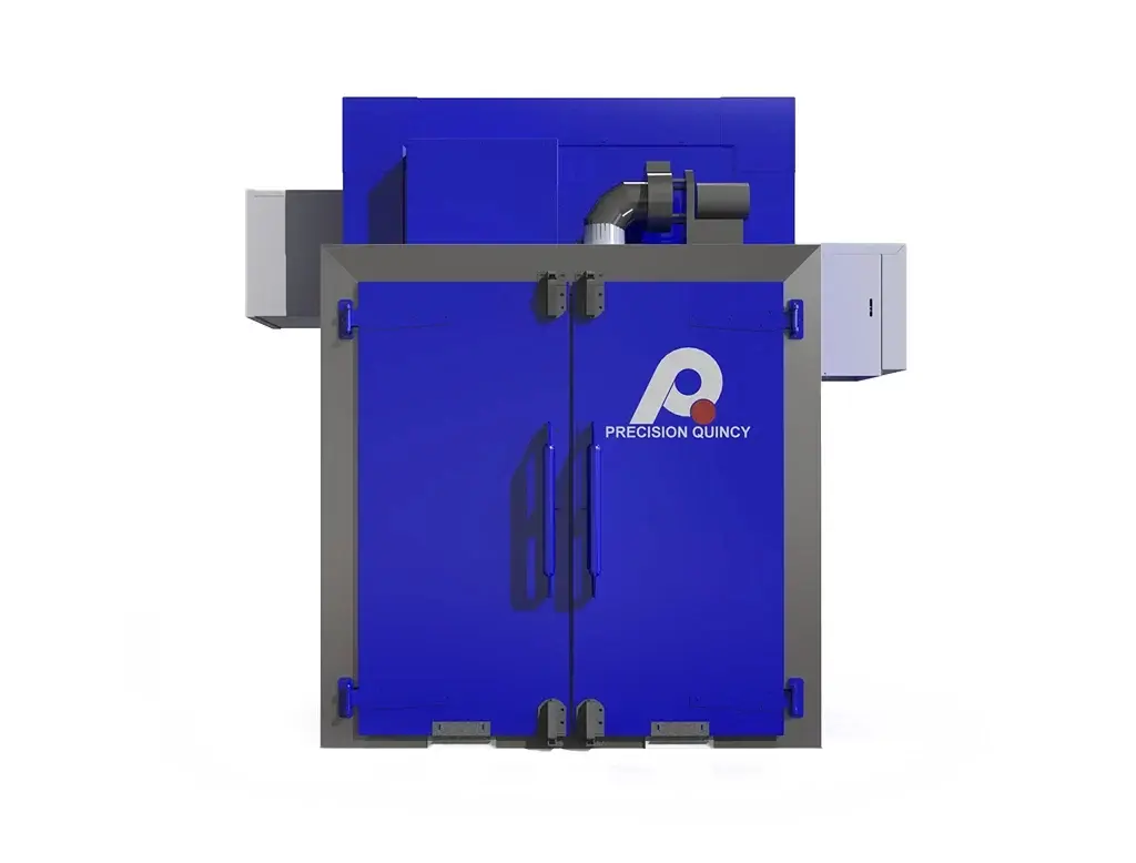
ELECTRICAL CABINET ARCHITECTURE
- High-voltage cabinet: power distribution, motor starters, and heater power components.
- Low-voltage control cabinet: PLC, control electronics, communication devices, and HMI interface hardware.
- Separation of high and low voltage improves safety, simplifies troubleshooting, and supports international electrical compliance requirements for the India installation.
- Electrical supply: 415V, 3-phase, 50 Hz; 246 A full load.
SHIPPING ARCHITECTURE
- Packed in breakbulk export crate; vacuum shrink wrap with desiccant protection for ocean freight to India.
- Shipping depth: 123.5 in. (operating depth 156 in.).
| OVEN CONFIGURATION | |
|---|---|
| Type | Continuous high-throughput indexing thermal processing system |
| Zones | Ramp Zone, Soak Zone, Cooling Zone |
| Total Stations | 435 |
| Station Pitch | 4 in. |
| Index Rate | 4 seconds per index |
| Max Throughput | ~900 parts/hour |
| Overall Height | 150.6 in. |
| Overall Width | 190 in. |
| Overall Depth | 156 in. (operating); 123.5 in. (shipping) |
| THERMAL HEAT POWER SYSTEM | |
|---|---|
| Ramp Zone Temp | Operating 410°F; maximum 500°F |
| Ramp Zone Power | 72 kW electric |
| Soak Zone Temp | Operating 385°F; maximum 500°F |
| Soak Zone Power | 36 kW electric |
| Heating Elements | 3 kW electric elements |
| Temperature Uniformity | ±10°F measured at nozzle discharge |
| RECIRCULATION / AIRFLOW SYSTEM | |
|---|---|
| Airflow Pattern | Vertical-down high-velocity impingement onto caps |
| Nozzle Discharge Velocity | ~4,000 FPM |
| Zone 1 (Ramp) Fan | 18 in. NYB PLR — 7,400 CFM; 7.5 HP |
| Zone 2 (Soak) Fans | (2) 18 in. NYB PLR — 14,800 CFM total; 15 HP |
| Zone Thermocouples | ~6 air-temperature monitoring TCs per heating zone (process verification and reject logic) |
| COOLING SYSTEM | |
|---|---|
| Cooling Fans | (2) vane-axial fans, acoustic-foam-shrouded |
| Fan Airflow | 5,425 CFM each |
| Fan Motor | 7.5 HP each |
| Cooling Coils | (2) — 52,950 BTU/hr each |
| Total Cooling Capacity | 105,900 BTU/hr |
| Noise Control | Foam-lined discharge tunnel at cooling exit; acoustic shroud on fan assemblies |
| CONVEYOR SYSTEM | |
|---|---|
| Conveyor Type | Single-strand chain-on-edge indexing conveyor |
| Chain | Hollow-pin with oversized rollers |
| Carrier Mounting | Bolted cap carriers |
| Drive | Helical bevel gearbox |
| Service Access | 5 sliding service doors (non-load side); duct modules slide out laterally |
| CONSTRUCTION MATERIALS / FINISH | |
|---|---|
| Shell Type | Structural reinforced insulated panels |
| Wall Thickness | 15 in. |
| Heating Section Skins | 18-gauge aluminized steel |
| Cooling Section | Non-insulated aluminized steel |
| CONTROLS & AUTOMATION | |
|---|---|
| PLC | Mitsubishi iQ-R R04CPU |
| Temperature Control | WRM temperature control system |
| HMI | (2) HMIs — operator station (load/unload) and low-voltage cabinet (maintenance/diagnostics) |
| Part Tracking | Per-part position tracking through all 435 stations; process status carried to unload |
| Acceptance Indication | Red/green visual indicator at unload station |
| Reject Verification | Drop chute with photoeye confirmation; conveyor cannot index until part clears |
| Over/Under Temp Monitor | Per-part-position over-temperature and under-temperature monitoring |
| ELECTRICAL SYSTEM | |
|---|---|
| Voltage | 415V, 3-phase |
| Frequency | 50 Hz |
| Full Load Amps | 246 A |
| Cabinet Split | High-voltage power cabinet + low-voltage control cabinet (separated for safety and compliance) |
| SHIPPING & INSTALLATION | |
|---|---|
| Shipping Method | Breakbulk export crate |
| Packaging | Vacuum shrink wrap with desiccant |
| Destination | India |
| PROCESS NOTES | |
|---|---|
| Product | Airbag inflator cap — cup-shaped metal component with thermally bonded foil hermetic seal |
| Application | Automotive safety restraint systems |
| Seal Criticality | Hermetic seal protects pyrotechnic inflator material from moisture intrusion — safety-critical automotive component |
| Qualification Period | ~3-month statistical validation period required before production release |
| NFPA Classification | NFPA 86 internal design standards |
